Download Files to the LMF - Site Specific BTS Files 68P09255A57-2 Table 3-10: Downloading and linking master-bts-cdma directory files for device loads Step Action NOTE If the current LMF code needs to be installed on the LMF PC, or if more information on file management, creating bts directories, or viewing CDF files is needed, refer to the.LMF Users Guide. The types of files that can be downloaded include code (.hex or .bin extension) and data (.dds extension) files.
Download Files to the LMF - Site Specific BTS Files 68P09255A57-2 Table 3-10: Downloading and linking master-bts-cdma directory files for device loads Step 8 Action Create softlinks to the device load and data load files in the bts-master-cdma directory using the following UNIX commands: ln -s /usr/lmf/bts-master-cdma/*.hex ln -s /usr/lmf/bts-master-cdma/*.hex.* ln -s /usr/lmf/bts-master-cdma/*.dds ln -s /usr/lmf/bts-master-cdma/*.dds.
Download Files to the LMF - Site Specific BTS Files 68P09255A57-2 Create BTS Specific CDF File Follow the steps outlined in Table 3-11 to create a BTS specific CDF file, if one cannot be obtained from the OMCR/CBSC. (This is an interim procedure and is subject to change). Table 3-11: Create BTS Specific CDF File Step Action ! CAUTION If you are not familiar with the UNIX vi editor, create a “dummy” CDF file, and practice making changes to it, prior to altering the “real” one.
Download Files to the LMF - Site Specific BTS Files 68P09255A57-2 Table 3-12: Update BTS Specific CDF File Device Load Version Step Action ! CAUTION If you are not familiar with the UNIX vi editor, create a “dummy” CDF file, and practice making changes to it, prior to altering the “real” one. * IMPORTANT CDF files obtained from the OMCR/CBSC are modified by DELTA information being appended to the end of the CDF file.
Download Files to the LMF - Site Specific BTS Files 68P09255A57-2 Table 3-13: Update Antenna Mapping Files Step Action ! CAUTION If you are not familiar with the UNIX vi editor, create a “dummy” CDF file, and practice making changes to it, prior to altering the “real” one. NOTE For more information on file management, creating bts directories, viewing/editing CDF files, refer to the LMF Users Guide. 1 View the antenna.
Operating the LMF 68P09255A57-2 Operating the LMF Basic Operation NOTE The terms “CDMA LMF” and “WinLMF” are interchangeable The CDMA LMF allows the user to work in the two following operating environments which are accessed using the specified desktop icon: Graphical User Interface (GUI) using the WinLMF icon Command Line Interface (CLI) using the WinLMF CLI icon 3 The GUI is the primary optimization and acceptance testing operating environment.
Operating the LMF 68P09255A57-2 CLI Format Conventions The CLI command can be broken down in the following way: Verb Device including device identifier parameters Switch Option parameters consisting of: - Keywords - Equals sign (=) between the keyword and the parameter value - Parameter values 3 Spaces are required between the verb, device, switch, and option parameters. A hyphen is required between the device and its identifiers. Following is an example of a CLI command.
Operating the LMF 68P09255A57-2 Table 3-14: BTS GUI Login Procedure Step 1 Action Start the LMF GUI environment by double clicking on the WinLMF desktop icon (if the LMF’s not running). NOTE If a warning similar to the following is displayed, select No, shut down other LMF sessions which may be running, and start the LMF GUI environment again: The CLI handler is already running.
Operating the LMF 68P09255A57-2 Table 3-15: BTS CLI Login Procedure Step 1 Action Double click the WinLMF CLI desktop icon (if the LMF CLI environment is not already running). NOTE If a BTS was logged into under a GUI session when the CLI environment was started, the CLI session will be logged into the same BTS, and step 2 is not required.
Operating the LMF 68P09255A57-2 Logging Out of a BTS from the CLI Environment Follow the procedure in Table 3-16 to logout of a BTS when using the CLI environment. Table 3-17: BTS CLI Logout Procedure Step Action * IMPORTANT 1 3 If the BTS is also logged into from a GUI running at the same time and further work must be done with it in the GUI, proceed to step 2. Logout of a BTS by entering the following command: logout bts- A response similar to the following will be displayed: LMF> 12:22:58.
Operating the LMF 68P09255A57-2 Figure 3-6: CDMA LMF Computer Common MMI Connections To FRU MMI port 8-PIN NULL MODEM BOARD (TRN9666A) 3 8-PIN TO 10-PIN RS-232 CABLE (P/N 30-09786R01) CDMA LMF COMPUTER RS-232 CABLE COM1 OR COM2 DB9-TO-DB25 ADAPTER FW00687 BTS Download Overview Before a BTS can operate, each equipped device must contain device initialization (ROM) code.
Operating the LMF 68P09255A57-2 ROM code can be downloaded to a device that is in any state. After the download is started, the device being downloaded will change to OOS_ROM (blue). The device will remain OOS_ROM (blue) when the download is completed. A compatible revision-level RAM code must then be downloaded to the device. Compatible code loads for ROM and RAM must be used for the device type to ensure proper performance.
Operating the LMF 68P09255A57-2 NOTE IMPORTANT: The MGLI must be successfully downloaded with RAM code and data, and in INS_ACT (bright green) status before downloading any other device. The RAM code download process for an MGLI automatically downloads data and then enables the MGLI. Verify GLI ROM Code Loads Devices should not be loaded with a RAM code version which is not compatible with the ROM code with which they are loaded.
Operating the LMF 68P09255A57-2 Table 3-20: Download and Enable MGLI and GLI Devices Step 3 Action 1b - Click on the BTS to be loaded. -- The BTS will be highlighted. 1c - Click the button next to the correct code version for the software release being used. -- A black dot will appear in the button circle. 1d - Click Save. 1e - Click OK to close each of the advisory boxes which appear. 2 Prepare to download code to the MGLI by clicking on the device.
Operating the LMF 68P09255A57-2 Table 3-21: Download RAM Code and Data to Non-GLI Devices Step Action 4 To download data, select the target CSM, MCC and/or BBX device(s). 5 Click Device in the BTS menu bar, and select select Download > Data in the pull-down menus. - A status report is displayed showing the results of the download for each selected device. Click OK to close the status report window when downloading is completed. 6 3 Aug 2002 SC 4812ET Optimization/ATP Manual Software Release R16.
System Tests 68P09255A57-2 System Tests Select CSM Clock Source A CSM can one of have three different clock sources. The Select CSM Source function can be used to select the clock source for each of the three inputs. This function is only used if the clock source for a CSM needs to be changed. The Clock Source function provides the following clock source options.
System Tests 68P09255A57-2 NOTE For RF-GPS, verify the CSM configured with the GPS receiver “daughter board” is installed in the frame’s CSM 1 slot before continuing. Follow the steps outlined in Table 3-23 to enable the CSMs installed in the C-CCP shelves. Table 3-23: Enable CSMs Step 1 Action Click on the target CSM. From the Device pull down, select Enable. 3 NOTE If equipped with two CSMs, enable CSM-2 first A status report is displayed confirming change in the device(s) status.
System Tests 68P09255A57-2 NOTE The MGLI and CSM must be downloaded and enabled, before downloading and enabling the MCC. Table 3-24: Enable MCCs Step Action 1 Click on the target MCC(s) or from the Select pull down menu choose MCCs. 2 From the Device menu, select Enable A status report is displayed confirming change in the device(s) status. Click OK to close the status report window.
System Tests 68P09255A57-2 The LFR requires an active external antenna to receive LORAN RF signals. Timing pulses are derived from this signal, which is synchronized to Universal Time Coordinates (UTC) and GPS time. The LFR can maintain system time indefinately after initial GPS lock. The HSO is a high stability 10 MHz oscillator with the necessary interface to the CSMs. The HSO is typically installed in those geographical areas not covered by the LORAN-C system.
System Tests 68P09255A57-2 Table 3-25: Test Equipment Setup (GPS & LFR/HSO Verification) Step Action 3 Reinstall CSM-2. 4 Start an MMI communication session with CSM-1 by using the Windows desktop shortcut icon (see Table 3-5) NOTE The LMF program must be running when a Hyperterminal session is started. 5 When the terminal screen appears press the Enter key until the CSM> prompt appears. 3 CAUTION Connect GPS antenna to the (GPS) RF connector ONLY.
System Tests 68P09255A57-2 GPS Initialization/Verification Follow the steps outlined in Table 3-26 to connect to CSM-1 installed in the C-CCP shelf, verifying that it is functioning normally.
System Tests 68P09255A57-2 Table 3-26: GPS Initialization/Verification Step Action 3 HSO information (underlined text above, verified from left to right) is usually the #1 reference source. If this is not the case, have the OMCR determine the correct BTS timing source has been identified in the database by entering the display bts csmgen command and correct as required using the edit csm csmgen refsrc command.
System Tests 68P09255A57-2 Table 3-26: GPS Initialization/Verification Step 5 Action Enter the following command at the CSM> prompt to verify that the GPS receiver is in tracking mode.
System Tests 68P09255A57-2 Table 3-26: GPS Initialization/Verification Step 7 Action If steps 1 through 6 pass, the GPS is good. * IMPORTANT If any of the above mentioned areas fail, verify that: - If Initial position accuracy is “estimated” (typical), at least 4 satellites must be tracked and visible (1 satellite must be tracked and visible if actual lat, log, and height data for this site has been entered into CDF file).
System Tests 68P09255A57-2 LORAN-C Initialization/Verification Table 3-27: LORAN-C Initialization/Verification Step Action 1 At the CSM> prompt, enter lstatus to verify that the LFR is in tracking mode.
System Tests 68P09255A57-2 Table 3-27: LORAN-C Initialization/Verification Step Action Note 2 Verify the following LFR information (highlighted above in boldface type): - Locate the “dot” that indicates the current phase locked station assignment (assigned by MM). - Verify that the station call letters are as specified in site documentation as well as M X Y Z assignment. - Verify the S/N ratio of the phase locked station is greater than 8.
Calibration and Test Equipment 68P09255A57-2 Calibration and Test Equipment Connecting Test Equipment to the BTS The following test equipment is required to perform calibration and ATP tests: LMF Communications system analyzer model supported by the LMF Power meter model supported by the LMF (required when using the HP 8921A/600 and Advantest R3465 analyzers) 3 Non-radiating transmit line termination load Directional coupler and in-line attenuator RF cables and adapters Refer to Table 3-28
Calibration and Test Equipment 68P09255A57-2 IS-95 A/B Testing Optimization and ATP testing for IS-95A/B sites or carriers may be performed using one of the following test equipment: CyberTest Advantest R3267 spectrum analyzer with R3562 signal generator and HP-437B or Gigatronics Power Meter Agilent E4406A transmitter test set with E4432B signal generator Agilent 8935 series E6380A communications test set (formerly HP 8935) Hewlett-Packard HP 8921 (with CDMA interface for 1.
Calibration and Test Equipment 68P09255A57-2 Test Equipment Connection Charts To use the following charts to identify necessary test equipment connections, locate the communications system analyzer being used in the COMMUNICATIONS SYSTEM ANALYZER columns, and read down the column. Where a dot appears in the column, connect one end of the test cable to that connector.
Calibration and Test Equipment 68P09255A57-2 CDMA2000 1X/IS-95A/B-capable Test Equipment Connections Table 3-29 depicts the interconnection requirements for currently available test equipment supporting both CDMA 2000 1X and IS-95A/B which meets Motorola standards and is supported by the LMF. Table 3-29: CDMA2000 1X/IS-95A/B Test Equipment Interconnection COMMUNICATIONS SYSTEM ANALYZER 3 SIGNAL EVEN SECOND SYNCHRONIZATION 19.
Calibration and Test Equipment 68P09255A57-2 Equipment Warm-up NOTE Warm-up BTS equipment for a minimum of 60 minutes prior to performing the BTS optimization procedure. This assures BTS stability and contributes to optimization accuracy. - Time spent running initial or normal power-up, hardware/firmware audit, and BTS download counts as warm-up time. WARNING Before installing any test equipment directly to any BTS TX OUT connector, verify there are no CDMA channels keyed.
Calibration and Test Equipment 68P09255A57-2 Figure 3-8: Cable Calibration Test Setup - CyberTest, Agilent 8935, Advantest R3465, and HP 8921A SUPPORTED TEST SETS CALIBRATION SET UP Motorola CyberTest A. SHORT CABLE CAL ÏÏÏ ÏÏÏÌ 3 ANT IN SHORT CABLE TEST SET RF GEN OUT Note: The 30 dB directional coupler is not used with the Cybertest test set. The TX cable is connected directly to the Cybertest test set. B.
Calibration and Test Equipment 68P09255A57-2 Figure 3-9: Cable Calibration Test Setup - Agilent E4406A/E4432B and Advantest R3267/R3562 SUPPORTED TEST SETS CALIBRATION SET UP A. SHORT CABLE CAL Agilent E4432B (Top) and E4406A (Bottom) SHORT CABLE RF OUTPUT 50 Ω TEST SET 3 B. RX TEST SETUP FOR TRDC N-N FEMALE ADAPTER RF INPUT 50 Ω RX CABLE SHORT CABLE NOTE: TEST SET 10 MHZ IN ON REAR OF SIGNAL GENERATOR IS CONNECTED TO 10 MHZ OUT (SWITCHED) ON REAR OF TRANSMITTER TESTER (FIGURE F-5).
Calibration and Test Equipment 68P09255A57-2 Figure 3-10: TX Calibration Test Setup - CyberTest (IS-95A/B) and Agilent 8935 (IS-95A/B and CDMA2000 1X) TEST SETS TRANSMIT (TX) SET UP Motorola CyberTest ÏÏÏ ÏÏÏ ÏÏÏÌ 3 FRONT PANEL POWER SENSOR NOTE: IF BTS IS EQUIPPED WITH DRDCS (DUPLEXED RX/TX SIGNALS), CONNECT THE TX TEST CABLE TO THE DRDC ANTENNA CONNECTOR. COMMUNICATIONS TEST SET 100-W ATT (MIN.
Calibration and Test Equipment 68P09255A57-2 Figure 3-11: TX Calibration Test Setup - Using Power Meter TEST SETS NOTE: THE HP8921A AND ADVANTEST R3465 CANNOT BE USED FOR TX CALIBRATION. A POWER METER MUST BE USED. TRANSMIT (TX) SET UP POWER SENSOR NOTE: IF BTS IS EQUIPPED WITH DRDCS (DUPLEXED RX/TX SIGNALS), CONNECT THE TX TEST CABLE TO THE DRDC ANTENNA CONNECTOR. POWER METER 100-W ATT (MIN.) NON-RADIA TING RF LOAD 3 TX TEST CABLE DIRECTIONAL COUPLER (30 DB) 50 Ω TERM .
Calibration and Test Equipment 68P09255A57-2 Figure 3-12: TX Calibration Test Setup - Agilent E4406A and Advantest R3567 (IS-95A/B and CDMA2000 1X) TEST SETS TRANSMIT (TX) SET UP Agilent E4406A POWER SENSOR NOTE: IF BTS IS EQUIPPED WITH DRDCS (DUPLEXED RX/TX SIGNALS), CONNECT THE TX TEST CABLE TO THE DRDC ANTENNA CONNECTOR. COMMUNICATIONS TEST SET RF INPUT 50 Ω OR INPUT 50 Ω 100-W ATT (MIN.
Calibration and Test Equipment 68P09255A57-2 Set-up for Optimization/ATP Figure 3-13 and Figure 3-14 show the test set connections for optimization/ATP tests. Figure 3-13: IS-95A/B Optimization/ATP Test Set-up, TRDC Shown - CyberTest and Advantest R3465 TEST SETS Optimization/ATP SET UP Motorola CyberTest SYNC MONITOR EVEN SEC TICK PULSE REFERENCE FROM CSM BOARD RF GEN OUT OR RF OUT 50Ω RX TEST CABLE FREQ MONITOR 19.
Calibration and Test Equipment 68P09255A57-2 Figure 3-14: IS-95A/B Optimization/ATP Test Setup - HP 8921A TEST SETS Optimization/ATP SET UP RX TEST CABLE Hewlett Packard Model HP 8921A W/PCS Interface (for 1900 MHz) SYNC MONITOR EVEN SEC TICK PULSE REFERENCE FROM CSM BOARD RF OUT ONLY NOTE: IF BTS IS EQUIPPED WITH DRDCS (DUPLEXED RX/TX SIGNALS), BOTH THE TX AND RX TEST CABLES CONNECT TO THE DRDC ANTENNA CONNECTOR. (SEE FIGURE 3-15.) FREQ MONITOR 19.
Calibration and Test Equipment 68P09255A57-2 Figure 3-15: IS-95A/B and CDMA2000 1X Optimization/ATP Test Setup With DRDCs Agilent Test Equipment TEST SETS Optimization/ATP SET UP RF OUTPUT 50 Ω OR DUPLEX OUT Agilent 8935 Series E6380A (formerly HP 8935) SYNC MONITOR EVEN SEC TICK PULSE REFERENCE FROM CSM BOARD 10 MHZ IN PATTERN TRIG IN RX TEST CABLE FREQ MONITOR 19.
Calibration and Test Equipment 68P09255A57-2 Figure 3-16: IS-95A/B and CDMA2000 1X Optimization/ATP Test Setup With DRDCs Advantest R3267/3562 Test Equipment TEST SETS Optimization/ATP SET UP RF OUT 50 Ω Advantest R3267 (Top) and R3562 (Bottom) SIGNAL GENERATOR MOD TIME BASE IN RX TEST CABLE TO EXT TRIG ON REAR OF SPECTRUM ANALYZER GPIB SPECTRUM ANALYZER 100-W ATT (MIN.
Calibration and Test Equipment 68P09255A57-2 Figure 3-17: IS-95A/B and CDMA2000 1X Optimization/ATP Test Setup With TRDCs Agilent Test Equipment TEST SETS Optimization/ATP SET UP SYNC MONITOR EVEN SEC TICK PULSE REFERENCE FROM CSM BOARD FREQ MONITOR 19.6608 MHZ CLOCK REFERENCE FROM CSM BOARD ÁÁ ÁÁ ÁÁ ÁÁ RF OUTPUT 50 Ω OR DUPLEX OUT RX TEST CABLE Agilent 8935 Model E6380A (formerly HP 8935) SIGNAL GENERATOR 10 MHZ IN PATTERN TRIG IN HP-IB TO GPIB BOX RF IN/OUT OR RF INPUT 50 Ω 100-W ATT (MIN.
Calibration and Test Equipment 68P09255A57-2 Figure 3-18: IS-95A/B and CDMA2000 1X Optimization/ATP Test Setup With TRDCs Advantest R3267/3562 Test Equipment TEST SETS Optimization/ATP SET UP RF OUT 50 Ω RX TEST CABLE Advantest R3267 (Top) and R3562 (Bottom) SIGNAL GENERATOR MOD TIME BASE IN TO EXT TRIG ON REAR OF SPECTRUM ANALYZER SYNTHE REF IN EXT TRIG IN GPIB SPECTRUM ANALYZER 3 100-W ATT (MIN.
Calibration and Test Equipment 68P09255A57-2 TX ATP Setup Figure 3-19 shows a typical TX ATP setup.
Calibration and Test Equipment 68P09255A57-2 Figure 3-20: Typical RX ATP Setup with Directional Coupler (shown with or without RFDS) COBRA RFDS Detail RX ANTENNA DIRECTIONAL COUPLERS RX RF FROM BTS FRAME 2 3 4 5 6 RX (RFM TX) 1 TX (RFM RX) RFDS TX (RFM RX) COUPLER OUTPUTS TO RFDS FWD(BTS) ASU1 (SHADED) CONNECTORS 3 RF FEED LINE TO TX ANTENNA REMOVED Connect RX test cable between the test set and the appropriate RX antenna directional coupler.
Loss/Gain Offset 68P09255A57-2 Loss/Gain Offset Background Proper test equipment setup ensures that the test equipment and associated test cables do not introduce measurement errors, and that measurements are correct. NOTE If the test set being used to interface with the BTS has been calibrated and maintained as a set, this procedure does not need to be performed. (Test Set includes LMF terminal, communications test set, additional test equipment, associated test cables, and adapters.
Loss/Gain Offset 68P09255A57-2 Prerequisites A Serial Connection and a Network Connection tab are provided for test equipment selection. The Serial Connection tab is used when the test equipment items are connected directly to the CDMA LMF computer via a GPIB box (normal setup). The Network Connection tab is used when the test equipment is to be connected remotely via a network connection.
Loss/Gain Offset 68P09255A57-2 Automatically Selecting Test Equipment in a Serial Connection Tab When using the auto-detection feature to select test equipment, the CDMA LMF examines which test equipment items are actually communicating with CDMA LMF. Follow the procedure in Table 3-31 to use the auto-detect feature. Table 3-31: Selecting Test Equipment Using Auto-Detect Step Action 1 From the Tools menu, select Options. The LMF Options window appears.
Loss/Gain Offset 68P09255A57-2 Table 3-32: Test Equipment Calibration Step Action 3 Click on Continue to close the Directions window. A status window is displayed. 4 Click on OK to close the status report window. Calibrating Cables The cable calibration function is used to measure the loss (in dB) for the TX and RX cables that are to be used for testing. A CDMA analyzer is used to measure the loss of each cable configuration (TX cable configuration and RX cable configuration).
Loss/Gain Offset 68P09255A57-2 Table 3-33: Cable Calibration Step Action 1 From the Util menu, select Cable Calibration. A Cable Calibration window is displayed. 2 Enter a channel number(s) in the Channels box. Multiple channels numbers must be separated with a comma, no space (i.e., 200,800). When two or more channels numbers are entered, the cables will be calibrated for each channel. Interpolation will be accomplished for other channels as required for TX calibration.
Loss/Gain Offset 68P09255A57-2 Figure 3-21: Calibrating Test Equipment Setup for TX Cable Calibration (Using Signal Generator and Spectrum Analyzer) Signal Generator Spectrum Analyzer SHORT TEST CABLE 100W NON-RADIA TING RF LOAD THIS WILL BE THE CONNECTION TO THE TX PORTS DURING TX CALIBRATION AND TO THE TX/RX PORTS DURING ATP TESTS.
Loss/Gain Offset 68P09255A57-2 Calibrating RX Cables Using a Signal Generator and Spectrum Analyzer Follow the procedure in Table 3-35 to calibrate the RX cables using the signal generator and spectrum analyzer. Refer to Figure 3-22, if required. Table 3-35: Calibrating RX Cables Using a Signal Generator and Spectrum Analyzer Step Action 1 Connect a short test cable to the spectrum analyzer and connect the other end to the Signal Generator.
Loss/Gain Offset 68P09255A57-2 Prerequisites Logged into the BTS Table 3-36: Setting Cable Loss Values Step 3 Action 1 Click on the Util menu. 2 Select Edit >Cable Loss > TX or RX. A data entry pop-up window will appear. 3 Click on the Add Row button to add a new channel number. Then click in the Channel # and Loss (dBm) columns and enter the desired values. 4 To edit existing values click in the data box to be changed and change the value.
Adjusting for loss 68P09255A57-2 Adjusting for loss Introduction Calibration compensates for normal equipment variations within the BTS and assures maximum measurement accuracy. RF Path Bay Level Offset Calibration Calibration identifies the accumulated gain in every transmit path (BBX slot) at the BTS site and stores that value in the CAL file. The BLOs are subsequently downloaded to each BBX. Each receive path starts at a BTS RX antenna port and terminates at a backplane BBX slot.
Adjusting for loss 68P09255A57-2 CAUTION Always wear a conductive, high impedance wrist strap while handling any circuit card/module. If this is not done, there is a high probability that the card/module could be damaged by ESD.
Adjusting for loss 68P09255A57-2 - The second breakdown of the array is per sector. Three sectors are allowed. Table 3-39: BTS.
Adjusting for loss 68P09255A57-2 Example: C[1]=384, odd cal entry = 1 ‘‘calibration point” C[2]=19102, even cal entry C[3]=777, C[4]=19086, . . C[19]=777, C[20]=19086, (since only two cal points were calibrated this would be repeated for the next 8 points) When the BBX is loaded with BLO data, the cal file data for the BBX is downloaded to the device in the order it is stored in the CAL file. TxCal data is sent first, C[1] - C[60].
Adjusting for loss 68P09255A57-2 At sites WITHOUT RFDS option, BLO is approximately 42.0 dB ±4.0 dB. A typical example would be TX output power measured at BTS (36.0 dBm) minus the BBX TX output level (approximately -6.0 dBm) would equate to 42 dB BLO. The TX Bay Level Offset at sites WITH the directional coupler option, is approximately 41.4 dB ±3.0 dB. TX BLO = Frame Power Output minus BBX output level. Example: TX output power measured at RFDS TX coupler (39.
Adjusting for loss 68P09255A57-2 Single-Sided BLO Normally valid values are some value plus-or-minus some offset. If single-sided BLO” is selected, the result will only be considered a success if it’s in the lower half of the range. If it was normally success from 37-47 (which is 42± 5), single-sided BLO” would make it a success only if the result was from 37-42.
Adjusting for loss 68P09255A57-2 Table 3-41: BTS TX Path Calibration Step Action NOTE Selecting PILOT (default) performs tests using a pilot signal only. Selecting STANDARD performs tests using pilot, synch, paging and six traffic channels. This requires an MCC to be selected. Selecting CDFPilot performs tests using the CDF value for pilot gain and IS-97 gain values for all the other channels included in the Standard pattern setting (paging, synch, and six traffic).
Adjusting for loss 68P09255A57-2 Table 3-42: Download BLO Step Action 1 Select the BBX(s) to be downloaded. 2 From the Device menu, select Download>BLO. A status report window displays the result of the download. NOTE 3 Selected device(s) do not change color when BLO is downloaded. Click OK to close the status report window. 3 Calibration Audit Introduction The BLO calibration audit procedure confirms the successful generation and storage of the BLO calibrations.
Adjusting for loss 68P09255A57-2 Test equipment and test cables are calibrated and connected for TX BLO calibration. LMF is logged into the BTS. Follow the procedure in Table 3-43 to perform the BTS TX Path Audit test. Table 3-43: BTS TX Path Audit Step 1 Action Select the BBX(s) to be audited. NOTE 3 If STANDARD or CDF is selected for Test Pattern, then at least one MCC must be also selected. 2 From the Tests menu, select TX>TX Audit.
Adjusting for loss 68P09255A57-2 Exception Handling In the event of a failure, the calibration procedure displays a FAIL message in the status report window and provides information in the Description field. Recheck the test setup and connection and re-run the test. If the tests fail again, note specifics about the failure, and refer to Chapter 6, Troubleshooting. 3 All Cal/Audit Test The Tests menu item, All Cal/Audit, performs the TX BLO Calibration and Audit test for a XCVR(s).
Adjusting for loss 68P09255A57-2 Table 3-44: All Cal/Audit Test Step 1 Action Select the BBX(s) to be tested. NOTE If STANDARD, CDF or CDFPILOT is selected for TEST PATTERN, then at least one MCC must be also selected. 2 From the Tests menu, select All Cal/Audit. 3 4 Select the appropriate carrier(s) displayed in the Channels/Carrier pick list. Press and hold the or key to select multiple items. Type the appropriate channel number in the Carrier n Channels box.
Adjusting for loss 68P09255A57-2 WARNING Editing the CAL file is not encouraged as this action can cause interface problems between the BTS and the LMF. To manually edit the CAL file you must first logout of the BTS. If you manually edit the CAL file and then use the Create Cal File function the edited information will be lost.
Adjusting for loss 68P09255A57-2 Asu1/2Equip - valid inputs are 0 or 1 0 = (default) Not equipped 1 = Equipped TestOrigDN - valid inputs are ’’’ (default) or a numerical string up to 15 characters. (This is the phone number the RFDS dials when originating a call. A dummy number needs to be set up by the switch, and is to be used in this field.) NOTE Any text editor may be used to open the bts-#.cdf file to verify, view, or modify data. Because the bts-#.
Adjusting for loss 68P09255A57-2 Table 3-46: RFDS Parameter Settings Step 3 Action 5a - To be sure it does not take control when the MGLI is disabled, manually disable the redundant GLI card by unseating it from the backplane connectors and sliding it partially out of the shelf slot. 5b - Click on the MGLI. 5c - Click on Device in the BTS menu bar, and select Disable from the pull-down menu. -- A status report window is displayed showing status of the operation.
Adjusting for loss 68P09255A57-2 Table 3-46: RFDS Parameter Settings Step Action 8b - Click on TSU in the BTS menu bar, and select Status TSU from the pull-down menu. -- A status report is displayed showing the software version number for the TSIC and SUA. 8c - Click OK to close the status report window. * IMPORTANT If the LMF displays an error message, check the following: Ensure AMR cable is correctly connected from the BTS to the RFDS. 3 Verify RFDS has power.
Adjusting for loss 68P09255A57-2 Table 3-47: Definition of Parameters IMSI MCC IMSI 11 12 These fields are obtained at the OMC using the following command: OMC000>disp bts-# imsi If the fields are blank, replace the IMSI fields in the NAM file to 0, otherwise use the values displayed by the OMC. MIN Phone Number These fields are the phone number assigned to the mobile. The ESN and MIN must be entered into the switch as well. NOTE This field is different from the TODN field in the bts-#.cdf file.
Adjusting for loss 68P09255A57-2 Table 3-49: Set Antenna Map Data Step Action 1 Click on Util in the BTS menu bar, and select Edit > Antenna Map... from the pull-down menus. - A tabbed data entry pop-up window will appear. 2 In the data entry pop-up window, click on the TX Antenna Map or RX Antenna Map tab to select the antenna map to be edited. 3 Locate the carrier and sector number for which data is to be entered or edited, and click in the column where entry or editing is needed.
Adjusting for loss 68P09255A57-2 Table 3-50: Set RFDS Configuration Data Step 3c 4 Action - Enter the desired data. To edit existing values click in the data box to be changed and change the value. NOTE Refer to the CDMA Help > Utility Menu > Edit-RFDS Configuration... section of LMF Help function on-line documentation for RFDS configuration data examples. 3 5 To delete a row, click on the row and then click on the Delete Row button.
Adjusting for loss 68P09255A57-2 Table 3-51: RFDS TSIC Calibration Channel Frequencies WARNING System Channel Calibration Points 800 MHz (A and B) 341 and 682 1.9 GHz 408 and 791 Before installing any test equipment directly to any TX OUT connector, verify that there are no CDMA channels keyed. Failure to do so can result in serious personal injury and/or equipment damage. 3 RFDS Calibration Procedure Prerequisites Test equipment has been selected.
Adjusting for loss 68P09255A57-2 Table 3-52: RFDS Calibration Step 1 In the LMF, select the FRAME tab. 2 If it is not selected (no black dot showing), click on the B button in the BTS menu bar to select it. 3 5 Select the BBX(s) assigned to the carrier(s) and sector(s) which will be used in RFDS calibration (refer to Table 1-5 for BBX carrier and sector assignments). Click on RFDS in the BTS menu bar, and select RFDS Calibration... from the pull-down menu.
Adjusting for loss 68P09255A57-2 Table 3-53: Program NAM Procedure Step Action 1 In the LMF, select the RFDS tab. 2 Select the SUA by clicking on it. 3 Click on TSU in the BTS menu bar, and select Program TSU NAM from the pull-down menu. - A NAM programming window will appear. 4 Enter the appropriate information in the boxes (see Table 3-47 and Table 3-48) . 5 Click on the OK button to display the status report. 6 Click on the OK button to close the status report window.
Alarms 68P09255A57-2 Alarms The alarms testing should be performed at a convenient point in the optimization/ATP process, since the LMF is necessary to ensure that the RF cabinet is receiving the appropriate alarms from the power cabinet. The SC 4812ET is capable of concurrently monitoring 10 customer defined input signals and four customer defined outputs, which interface to the 50-pin punchblock. All alarms are defaulted to “Not Equipped” during ATP testing.
Alarms 68P09255A57-2 Table 3-54: Heat Exchanger Alarm Step Action 1 Turn circuit breaker “B” of the Heat Exchanger circuit breakers OFF. This will generate a Heat Exchanger alarm, ensure that the LMF reports the correct alarm condition in the RF Cabinet. 2 Alarm condition will be reported as BTS Relay #25 - “Heat Exchanger Alarm” makes contact. 3 Turn the circuit breaker “B” ON. Ensure that the alarm condition is now removed. NOTE The Heat Exchanger will go through the Start Up sequence.
Alarms 68P09255A57-2 Table 3-57: Minor Alarm Step 3 Action 1 Turn the Temperature Compensation Panel (TCP) power switch OFF. This will generate a minor alarm. Verify that the minor alarm LED (amber) is illuminated on the Meter Alarm Panel and the LMF reports this minor alarm. 2 Alarm condition will be reported as BTS Relay #24 “Minor Alarm” makes contact. 3 Turn the TCP power switch ON. The alarm condition should clear.
Alarms 68P09255A57-2 Table 3-59: Multiple Rectifier Failure or Major Alarm Step Action 3 Verify that the LMF reports both alarm conditions. (BTS #29, BTS #21, and BTS #24) 4 Turn the AC breaker for the 1st shelf ON. Verify that all alarms have cleared. 5 Return the rectifier module to its original location. This completes the alarm test on the power cabinet.
Alarms 68P09255A57-2 Battery Over Temperature Alarm (Optional) CAUTION Use special care to avoid damaging insulation on cables, or damaging battery cases when using a power heat gun. Table 3-62 gives instructions on testing the battery over temperature alarm system. Table 3-62: Battery Over Temperature Alarm Step 3 Action 1 Use a low powered heat gun and gently heat the battery over temperature sensor (see location in Figure 3-23). Do Not hold the hot air gun closer than 7.6 cm (3 in.
Alarms 68P09255A57-2 Figure 3-23: Battery Over-temperature Sensor 3 FW00408 Buss Bar 6 AWG Cables Battery Overtemp Sensor Negative Temperature Compensation Sensor Aug 2002 SC 4812ET Optimization/ATP Manual Software Release R16.1.x.
Alarms 68P09255A57-2 Rectifier Over Temperature Alarm NOTE This is connector J8 on the rear of the Meter Alarm Panel itself, this is not connector J8 on the connector bulkhead at the rear of the cabinet. Table 3-63 gives instructions on testing the battery over temperature alarm system. Table 3-63: Rectifier Over Temperature Alarm 3 Step 1 Action Remove the J8 link on the rear of the Meter Alarm Panel (see Figure 3-24 for J8 location).
Before Leaving the site 68P09255A57-2 Before Leaving the site Table 3-64 gives instructions on what to check before leaving the site. Table 3-64: Check Before Leaving the Site Step Action 1 Verify that ALL battery circuit breakers (for occupied shelves) are CLOSED (pushed in). 2 Verify that the Heat Exchanger is running. 3 Verify that the Meter Alarm Panel and TCP modules are switched ON. 4 Verify that the Battery Test Switch on the Meter Alarm Panel is in the OFF position.
Before Leaving the site 68P09255A57-2 Notes 3 3-104 SC 4812ET Optimization/ATP Manual Software Release R16.1.x.
Chapter 4 4 Automated Test Procedures (ATP) Aug 2002 SC 4812ET Optimization/ATP Manual Software Release R16.1.x.
ATP Tests 68P09255A57-2 ATP Tests Introduction The Automated Acceptance Test Procedure (ATP) allows Motorola Cellular Field Engineers (CFEs) to run automated acceptance tests on all equipped BTS subsystem devices using the Local Maintenance Facility (LMF) and supported test equipment per the current Cell Site Data File (CDF) assignment. The results of these tests (at the option of the operator) are written to a file that can be printed.
ATP Tests 68P09255A57-2 In the unlikely event that the BTS passes these tests but has a forward link problem during normal operation, the CFE should then perform the additional TX tests for troubleshooting: TX spectral mask, TX rho, and TX code domain. NOTE Refer to Chapter 3 for detailed information on test set connections for calibrating equipment, cables and other test set components, if required.
ATP Tests 68P09255A57-2 TX/RX OUT Connections NOTE Table:note. Note 10pt Helvetica Many of the acceptance test procedures require taking measurements at the TX OUT (BTS/RFDS) connector. At sites with RFDS, all measurements are through the RFDS directional coupler TX OUT connector. ATP Test Procedure There are three different ATP testing options that can be performed to completely test a BTS. Depending on your requirements, one of the following ATP testing options should be run.
ATP Tests 68P09255A57-2 Individual Acceptance Tests The following individual ATP tests can be used to verify the results of specific tests: Spectral Purity TX Mask This test verifies that the transmitted CDMA carrier waveform, generated on each sector, meets the transmit spectral mask specification with respect to the assigned CDF file values.
ATP Tests 68P09255A57-2 ATP Test Procedure Table 4-1 describes the step-by-step procedures to run any APT Test. Table 4-1: ATP Test Procedure Step Action 1 Select the device(s) to be tested. 2 From the Tests menu, select the desired test. 3 Select the appropriate carrier(s) (carrier - bts# - sector# - carrier#) displayed in the Channels/Carrier pick list. To select multiple items, hold down the or key while making the selections.
ATP Tests 68P09255A57-2 NOTE TX output power is set to +40 dBm by setting BTS power level to +33.5 dBm to compensate for 6.5 dB increase from pilot gain set to 541. The calibrated communications test set measures and returns the attenuation level of all spurious and IM products in a 30 kHz resolution bandwidth with respect to the mean power of the CDMA channel, measured in a 1.23 MHz bandwidth, in dB, verifying that results meet system tolerances at the following test points: 1.
ATP Tests 68P09255A57-2 Background: Rho Test This test verifies the transmitted Pilot channel element digital waveform quality of each BBX2 carrier keyed up at a specific frequency per the current CDF file assignment. All tests are performed using the external calibrated test set controlled by the same command. All measurements are via the appropriate TX OUT (BTS/RFDS) connector. The Pilot Gain is set to 262 for each antenna, and all channel elements from the MCCs will be forward link disabled.
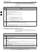
ATP Tests 68P09255A57-2 Background: Code Domain Power Test This test verifies the Code Domain Power/Noise of each BBX2 carrier keyed up at a specific frequency per the current CDF file assignment. All tests are performed using the external calibrated test set controlled by the same command. All measurements are via the appropriate TX OUT (BTS/RFDS) connector.
ATP Tests 68P09255A57-2 Figure 4-2: Code Domain Power and Noise Floor Levels Pilot Channel PILOT LEVEL MAX OCNS CHANNEL 8.2 dB 12.2 dB MAX OCNS SPEC. Active channels MIN OCNS SPEC. MIN OCNS CHANNEL MAX NOISE FLOOR MAXIMUM NOISE FLOOR: < -27 dB SPEC. Inactive channels Walsh 0 1 2 3 4 5 6 7 ... 64 Showing all OCNS Passing 4 Pilot Channel PILOT LEVEL FAILURE - EXCEEDS MAX OCNS SPEC. 8.2 dB 12.2 dB MAX OCNS SPEC. Active channels MIN OCNS SPEC. FAILURE - DOES NOT MEET MIN OCNS SPEC.