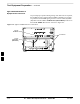
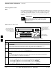
Test Equipment Preparation – continued Agilent E4406A/E4432B Test Equipment Interconnection To provide proper operation during testing when both units are required, the 10 MHz reference signal from the E4406A transmitter test set must be provided to the E4432B signal generator. Connect a BNC (M)–BNC (M) cable from the E4406A 10 MHz OUT (SWITCHED) connector to the E4432B 10MHz IN connector as shown in Figure F-5.
Manual Cable Calibration Calibrating Test Cable Setup using HP PCS Interface (HP83236) Table F-9 covers the procedure to calibrate the test equipment using the HP8921 Cellular Communications Analyzer equipped with the HP83236 PCS Interface. NOTE This calibration method must be executed with great care. Some losses are measured close to the minimum limit of the power meter sensor (–30 dBm).
Manual Cable Calibration – continued Table F-9: Calibrating Test Cable Setup (using the HP PCS Interface) Step F Action 8 Set RF Generator level: – Position the cursor at RF Generator Level and select it. – Enter –10 using the numeric keypad; press [Enter] and the screen will go blank. – When the screen reappears, the value –10 dBm will be displayed on the RF Generator Level line.
Manual Cable Calibration – continued Table F-9: Calibrating Test Cable Setup (using the HP PCS Interface) Step Action 19 After all components are calibrated, reassemble all components together and calculate the total test setup loss by adding up all the individual losses: Example: Total test setup loss = –1.4 –29.8 –20.1 = –51.3 dB. This calculated value will be used in the next series of tests. 20 Under Screen Controls press the TESTS button to display the TESTS (Main Menu) screen.
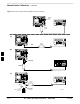
Manual Cable Calibration – continued Figure F-6: Cable CalibrationUsing HP8921 with PCS Interface MEMORY CARD SLOT POWER SENSOR (A) (A) POWER SENSOR (B) F (B) 20 dB / 20 WATT ATTENUATOR POWER SENSOR (C) POWER SENSOR (C) 150 W NON–RADIATING RF LOAD F-14 30 dB DIRECTIONAL COUPLER SC 4812ET BTS Optimization/ATP — CDMA LMF FW00292 Jan 2002
Manual Cable Calibration – continued Calibrating Test Cable Setup using Advantest R3465 NOTE Be sure the GPIB Interface is OFF for this procedure. Advantest R3465 Manual Test setup and calibration must be performed at both the TX and RX frequencies. Table F-10: Procedure for Calibrating Test Cable Setup Using Advantest R3465 Step Action * IMPORTANT – This procedure can only be performed after test equipment has been allowed to warm–up and stabilize for a minimum of 60 minutes.
Manual Cable Calibration – continued Table F-10: Procedure for Calibrating Test Cable Setup Using Advantest R3465 Step 16 Action Disconnect the power meter sensor from the R3561L RF OUT jack. * IMPORTANT The Power Meter sensor’s lower limit is –30 dBm. Thus, only components having losses < 30 dB should be measured using this method. For best accuracy, always re–zero the power meter before connecting the power sensor to the component being calibrated.
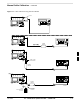
Manual Cable Calibration – continued Figure F-7: Cable Calibration using Advantest R3465 RF OUT POWER SENSOR (A) & (B) POWER SENSOR F (C) 20 DB / 2 WATT ATTENUATOR POWER SENSOR (C) POWER SENSOR (D) 100 W NON–RADIATING RF LOAD Jan 2002 FW00320 30 DB DIRECTIONAL COUPLER SC 4812ET BTS Optimization/ATP — CDMA LMF F-17
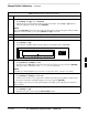
Manual Cable Calibration – continued Calibrating HP 437 Power Meter Precise transmit output power calibration measurements are made using a bolometer–type broadband power meter with a sensitive power sensor. Follow the steps outlined in Table F-11 to enter information unique to the power sensor before calibrating the test setup. Refer to Figure F-8 as required. IMPORTANT * This procedure must be done in conjunction with the automated calibration to enter power sensor specific calibration values.
Manual Cable Calibration – continued Table F-11: Power Meter Calibration Procedure Step 4 Action Perform the following to set or verify the correct power sensor model: – Press [SHIFT] then [ ] to select SENSOR. – Identify the power sensor model number from the sensor label. Use the [ ] or [ ] button to select the appropriate model; then press [ENTER]. NOTE Be sure the PWR REF (power reference) output is OFF (observe that the triangular indicator is NOT displayed as shown in Step 7).
Manual Cable Calibration – continued Calibrating Gigatronics 8541C power meter Precise transmit output power calibration measurements are made using a bolometer–type broadband power meter with a sensitive power sensor. Follow the steps in Table F-12 to enter information unique to the power sensor. Table F-12: Calibrate Gigatronics 8541C Power Meter Step Action ! CAUTION Do not connect/disconnect the power meter sensor cable with AC power applied to the meter.
Manual Cable Calibration – continued Figure F-9: Gigatronics 8541C Power Meter Detail CONNECT POWER SENSOR TO CALIBRATOR POWER REFERENCE WHEN CALIBRATING/ZEROING UNIT CONNECT POWER SENSOR WITH POWER METER TURNED OFF FRONT View AC POWER GPIB CONNECTION REAR View FW00564 F Jan 2002 SC 4812ET BTS Optimization/ATP — CDMA LMF F-21
Manual Cable Calibration – continued Notes F F-22 SC 4812ET BTS Optimization/ATP — CDMA LMF Jan 2002
Appendix G: In–Service Calibration Appendix Content Introduction . . . . . . . . . . . . . . . . . . . . . . . . . . . . . . . . . . . . . . . . . . . . . . . . . . . . . Purpose . . . . . . . . . . . . . . . . . . . . . . . . . . . . . . . . . . . . . . . . . . . . . . . . . Equipment Warm up . . . . . . . . . . . . . . . . . . . . . . . . . . . . . . . . . . . . . . . G-1 G-1 G-1 Power Delta Calibration . . . . . . . . . . . . . . . . . . . . . . . . . . . . . . . . . . . . . . . . . . .
Table of Contents – continued Notes G SC 4812ET BTS Optimization/ATP — CDMA LMF Jan 2002
Introduction Purpose This procedure is a guide to expanding your system with multiple carriers while the system remains in service. This procedure also allows you to perform on site maintenance (replace defective boards and recalibrate) while the remainder of the site stays in service. Motorola recommends that you perform this procedure during a maintenance window. This procedure cannot be performed on BTSs with 4–to–1 combiners. The procedure can only be performed on one side of the BTS at one time.
Power Delta Calibration Power Delta Calibration Introduction The In–service calibration procedure has several differences from a normal calibration procedure. One of these is the use of a spectrum analyzer instead of a power meter to measure power. Power meters are broadband measurement devices and cannot be used to measure power during In–service Calibration since other carriers are operating. A spectrum analyzer can be used because it measures power at a given frequency.
Power Delta Calibration – continued Table G-1: HP8921A Power Delta Calibration Procedure Step 5 Action Turn off the source HP8921A signal output, and disconnect the HP437B. NOTE Leave the settings on the source HP8921A for convenience in the following steps. 6 Connect the short RF cable between the source HP8921A Duplex Out port and the measuring HP8921A RF–IN port (see Figure G-2). 7 Ensure that the source HP8921A settings are the same as in Step 2.
Power Delta Calibration – continued Figure G-1: Delta Calibration Setup – HP8921A to HP437B HP 8921A HP437B SENSOR Power Sensor DUPLEX OUT Short RF Cable FW00801 Figure G-2: Delta Calibration Setup – HP8921A to HP8921A Measurement HP8921A Source HP8921A DUPLEX OUT RF IN/OUT Short RF Cable FW00802 Advantest R3465 Power Delta Calibration G Follow the procedure in Table G-2 to perform the Advantest 3465 Power Delta Calibration procedure.
Power Delta Calibration – continued Table G-2: Advantest Power Delta Calibration Procedure Step Action 5 Set the frequency to the desired value using the keypad entry keys. 6 Press the LEVEL key in the Entry area of the control panel. 7 Set the LEVEL to 0 dBm using the keypad entry keys. 8 Verify the Mod CRT menu key is highlighting OFF, if not press the Mod key to toggle it OFF. 9 Verify the Output CRT menu key is highlighting OFF, if not press the Output key to toggle it OFF.
Power Delta Calibration – continued Table G-2: Advantest Power Delta Calibration Procedure Step Action 30 Press the return CRT menu key. 31 Press the SPAN key in the Entry area of the control panel. 32 Press the Zero Span CRT menu key. 33 Press the BW key in the Entry area of the control panel. 34 Press the RBW CRT menu key to highlight MNL. using keypad entry keys enter 30 kHz. 35 Set RBW to 30 kHz using keypad entry keys. 36 Press the VBW CRT menu key to highlight MNL.
Power Delta Calibration – continued Figure G-4: Delta Calibration Setup – R3561L to R3465 RF OUT R3561L Short RF Cable R3465 INPUT FW00804 HP8935 Power Delta Calibration Follow the procedure in Table G-3 to perform the HP8935 Power Delta Calibration procedure. Table G-3: HP8935 Power Delta Calibration Procedure Step Action * IMPORTANT Perform this procedure after test equipment has been allowed to warm–up and stabilize for a minimum of 60 minutes.
Power Delta Calibration – continued Table G-3: HP8935 Power Delta Calibration Procedure Step Action 8 Set the measuring HP8935 as follows: – Measure mode to CDMA Anl – Frequency to the CDMA calibration target frequency – Input Attenuation to 0 dB – Input port to RF–IN – Gain to Auto – Anl Dir to Fwd 9 Turn on the source HP8935 signal output. 10 Set the Chn Pwr Cal to Calibrate and select to calibrate.
Power Delta Calibration – continued Figure G-6: Delta Calibration Setup – HP8935 to HP8935 Hewlett–Packard Model HP 8935 DUPLEX OUT RF IN/OUT Short RF Cable FW00806 Agilent E4406A Power Delta Calibration The Agilent E4406A transmitter tester and E4432B signal generator test equipment combination can be used for CDMA 2000 as well as IS–95A/B operation modes.
Power Delta Calibration – continued Table G-4: Agilent E4406A Power Delta Calibration Procedure Step Action 4 On the E4432B, press RF On/Off to toggle the RF output to RF ON. – Note that the RF On/Off status in the screen display changes. 5 Measure and record the value reading on the HP437 power meter as result A____________________. 6 On the E4432B, press RF On/Off to toggle the RF output to RF OFF. – Note that the RF On/Off status in the screen display changes.
Power Delta Calibration – continued Table G-4: Agilent E4406A Power Delta Calibration Procedure Step Action 12 Calculate the Power Calibration Delta value. The delta value is the power meter measurement minus the Agilent measurement. Delta = A – B Example: Delta = –0.70 dBm – (–1.25 dBm) = 0.55 dBm Example: Delta = 0.26 dBm – 0.55 dBm = –0.29 dBm These examples are included to show the mathematics and do not represent actual readings.
In–Service Calibration In–Service Calibration IMPORTANT * This feature does NOT have fault tolerance at this time. The system has no safe–guards to stop you from doing something that will take the BTS out of service. If possible, perform this procedure during a maintenance window. Follow the procedures in this section precisely, otherwise the entire BTS will most likely go OUT OF SERVICE. At the CBSC, only perform operations on expansion hardware when it is in the OOS_MANUAL state.
In–Service Calibration – continued The Power Delta Calibration has been performed (see Table G-1, Table G-2, or Table G-3). Figure G-9: Optimization/ATP Test Setup Using RFDS TEST SETS Optimization/ATP SET UP Hewlett–Packard Model HP 8935 SYNC MONITOR EVEN SEC TICK PULSE REFERENCE FROM CSM BOARD DUPLEX OUT FREQ MONITOR 19.
In–Service Calibration – continued Figure G-10: IS–95 A/B/C Optimization/ATP Test Setup Using RFDS TEST SETS Optimization/ATP SET UP Advantest R3267 (Top) and R3562 (Bottom) NOTE: IF BTS RX/TX SIGNALS ARE DUPLEXED: BOTH THE TX AND RX TEST CABLES CONNECT TO THE DUPLEXED ANTENNA GROUP. RX TEST CABLE TO EXT TRIG ON REAR OF SPECTRUM ANALYZER ANTENNA INPUT 50 OHM 20 DB PAD (FOR 1.7/1.9 GHZ) 10 DB PAD (FOR 800 MHZ) MOD TIME BASE IN (EXT REF IN) RF OUT 50 OHM NOTE: FREQ MONITOR 19.
In–Service Calibration – continued Follow the procedure in Table G-5 to perform the In–Service Calibration. Table G-5: In–Service Calibration Step Action * IMPORTANT Perform this procedure after test equipment has been allowed to warm–up and stabilize for a minimum of 60 minutes. 1 Set up the LMF for In–Service Calibration: – Start the LMF by double–clicking the LMF icon on the Windows desktop. – Click Tools>Options from the menu bar at the login screen.
In–Service Calibration – continued Table G-5: In–Service Calibration Step 4 Action Add the spectrum analyzer power delta to the Cable Loss. – To view the cable loss file, click Util>Examine>Cable Loss>TX or RX. – Add the value computed in Table G-1, Table G-2, or Table G-3 to the TX Cable Loss. NOTE Be sure to include the sign of the value. The following examples are included to show the mathematics and do not represent actual readings: – Example: 5.65 dBm + 0.55 dBm = 6.20 dBm – Example: 5.65 dBm + (–0.
In–Service Calibration – continued Table G-5: In–Service Calibration Step Action ! CAUTION Perform the In–service Calibration procedure on OOS devices only. 8 Select the desired test: – Select the target BBX(s) on the C–CCP cage picture. – Click Tests>[desired test] from the menu bar at the main window. – Select the target carrier and confirm the channel number in the pop up window. – Leave the Verify BLO check box checked. – From the Test Pattern pick list, select a test pattern.
In–Service Calibration – continued Notes G G-18 SC 4812ET BTS Optimization/ATP — CDMA LMF Jan 2002
Appendix H: RF Cabinet Interconnect Cables Appendix Content SC 4812ET Inter−Cabinet Cabeling . . . . . . . . . . . . . . . . . . . . . . . . H'1 C−CCP Cables and Cable Connectors . . . . . . . . . . . . . . . . . . . . . . H'4 RF Cabinet LPA Cables . . . . . . . . . . . . . . . . . . . . . . . . . . . . . . . . . . . H'7 LPAC Cabling . . . . . . . . . . . . . . . . . . . . . . . . . . . . . . . . . . . . . . . . . . . H'11 ETIB Cables and Cable Connectors . . . . . . . . . . . . . . . . . . . . . .
Table of Contents – continued Notes H SC 4812ET BTS Optimization/ATP — CDMA LMF Jan 2002
RF Cabinet Interconnect Cables SC 4812ET Intra–Cabinet Cabling This appendix provides the identification and location of the cables connecting the components which make up the SC 4812ET RF cabinet. The number of cables and components incorporated in the RF cabinet will vary depending on the the manner in which the cabinet is equipped. For example, a 3 sector, 2 carrier system will require less components and less cables than a 6 sector 2 carrier system.
RF Cabinet Interconnect Cables – continued Table H-1 : 4812ET RF CABINET INTER–CONNECT CABLES C–CCP Cables (cont) CABLE # FROM NOTEs TO 3064899A04 LAN I/O B in See Figure H-1 & Figure H-5 C–CCP LAN I/O B In 3086033H03 GPS Surge Arrestor See Figure H-1 & Figure H-5 C–CCPBackplane 3064899A04 LAN I/O B in See Figure H-1 & Figure H-5 C–CCP LAN I/O B In 3064899A03 C–CCP LAN I/O A Out See Figure H-1 & Figure H-5 LAN I/O A Out 3064899A03 C–CCP LAN I/O B Out See Figure H-1 & Figure H-5 LAN
RF Cabinet Interconnect Cables – continued Table H-1 : 4812ET RF CABINET INTER–CONNECT CABLES 3086505H01 DC Cable (DC Power Dist) See Figure H-1 & Figure H-19 EBA Blower Assembly 3086566H01 LPAC See Figure H-1 & Figure H-8 1 Cable to each LPA Bk Pln 3086569H01 Door Intrusion Alarm See Figure H-5 & Figure H-19 Door Switch 3086655H02 LPAC See Figure H-8, Figure H-5 & Figure H-19 ETIB Figure H-1: 4812ET RF Cabinet Internal FRU Locations (See Figure H-8, Figure H-9), and Figure H-10) EBA RFDS E
RF Cabinet Interconnect Cables – continued C–CCP Cables and Cable Connectors The C-CCP Shelf assembly consists of the C-CCP Shelf and the attached backplane with cables and connectors (see Figure H-2 and Figure H-3). The C–CCP shelf contains all of the CDMA unique functions within the SC 4812ET RF frame.
RF Cabinet Interconnect Cables – continued Figure H-2: C-CCP Shelf Cable Numbers and Connectors (To J1 connector on the ETIB) Cable # 3086086H02 (To SPAN A I/O connector on the Bulkhead) Cable # 3086001H02 ALARMS (To J2 connector on the ETIB) Cable # 3086000H02 (To SPAN B I/O connector on the Bulkhead) Cable # 3086001H02 SITE I/O SPAN B SPAN A Cable # 3086366H02 LAN I/O A Cable # 3064899A04 LAN I/O B Cable # 3064899A04 MPC/EMPC–1 BBX2–6 BBX2–13 BBX2–5 BBX2–4 BBX2–3 BBX2–2 BBX2–1 MCC24–6 M
RF Cabinet Interconnect Cables – continued Figure H-3: C–CCP Backplane (To J1 connector on the ETIB) Cable # 3086086H02 (To SPAN A I/O connector on the Bulkhead) Cable # 3086001H02 (To J2 connector on the ETIB) Cable # 3086000H02 (To SPAN B I/O connector on the Bulkhead) Cable # 3086001H02 SYSTEM LED Cable # 4886044H01 HSO/LFR LAN IN A LAN IN B CCCP Power 3064809A01 Cable # 3086366H02 Cable # 3064899A04 Cable # 3064899A04 To LAN I/O connectors on the Bulkhead Cable # 3064794A03 LPAC (To the C–CCP c
RF Cabinet Interconnect Cables – continued RF Cabinet LPA Cables There can be a maximum of 16 LPAs in an RF cabinet. The connections shown are for one LPA backplane which controls four LPAs. The remaining LPAs are connected in the same manner. Refer to Figure H-4, through Figure H-8 for the cables connected to the LPAs in the 4812ET RF cabinet.
RF Cabinet Interconnect Cables – continued Figure H-5: BTS Combiner to LPA Backplane Cables LPA Backplane EBA RFDS LPA–1 ETIB TX OUT1 5 RU RACK SPACE Cable 3064735A10 (3 each) TX IN 1 TX OUT2 LPA–2 TX IN2 TX IN 3 LPA–3 TX OUT3 SC 4812ET BTS RF Cabinet LPA–4 4B 4A 1B 1A S1 C1 S2 S3 S1 C2 LPA–1 S2 5B 5A 2B 2A S3 S1 C3 S2 LPA–2 S3 6B H 6A 3B 3A S1 C4 S2 S3 FROM APPROPRIATE LPA LPA 1, LPA 2, LPA 3, LPA 4 LPA–3 LPA–4 BACK H-8 SC 4812ET BTS Optimization/ATP — CDMA LMF
RF Cabinet Interconnect Cables – continued Figure H-6: Combiner to LPA Backplane/LPA Backplane To CIO Board Cables LPA Backplane 1 EBA RFDS LPA–1 ETIB TX OUT1 5 RU RACK SPACE TX IN 1 TX OUT2 Cable 3064735A10 (3 each) LPA–2 RED TX IN2 ORANGE YELLOW TX IN 3 LPA–3 TX OUT3 SC 4812ET BTS RF Cabinet LPA–4 4B 4A 1B 1A S1 C1 S2 TO J15 on CIO Board (See Figure H-7) Cable 3064795A05 S3 S1 C2 LPA–1 S2 5B 5A 2B 2A S3 S1 C3 TX OUT1 S2 TX IN 1 TX OUT2 S3 6B 6A 3B 3A S1 C4 LPA–2 GRE
RF Cabinet Interconnect Cables – continued Figure H-7: Components Located on CIO Card SC 4812ET RF Cabinet ETIB EBA RFDS 5 RU RACK SPACE RX EXP A J12 RX EXP B J13 TX BTS 1–6 J15 BTS 7–12 M/F 1–6 J14 TX FW00237 H H-10 SC 4812ET BTS Optimization/ATP — CDMA LMF Jan 2002
RF Cabinet Interconnect Cables – continued LPAC Cabling The LPAC module provides the communication interface from the ETIB and C–CCP to the LPA through the trunking backplane. The LPAC interface board is contained in a protective housing which is mounted on the RF cabinet frame behind the ETIB module. See Figure H-3, Figure H-8 and Figure H-9 for connecting cables and connector locations. The LPAC is located internally to the frame as shown in Figure H-1.
RF Cabinet Interconnect Cables – continued ETIB Cables and Cable Connectors The ETIB module (see Figure H-9) provides the interface for the LPA’s through the LPAC, punchblock, heat exchanger and alarms to the C–CCP backplane. The ETIB interface board is contained in a protective housing which is mounted on the RF cabinet frame. The ETIB is located internally to the frame as shown in Figure H-1.
RF Cabinet Interconnect Cables – continued SPAN I/O Cable Connection Diagram The SPAN I/O card provides the frame interface and secondary surge protection for the T1 lines. There are two span cards in an RF cabinet. SPAN I/O A supports spans A, C, and E. SPAN I/O B supports span B, D, and F. See Figure H-10 for SPAN cables and cable connections. The SPAN I/O is located internally to the frame as shown in Figure H-1. . . .
RF Cabinet Interconnect Cables – continued Figure H-10: SPAN I/O Cables and Connectors 20 Pair RGD Punchblock Board (RGPS) SPAN I/O (A & B) Interface Module (Located Behind the LPAC Module, See Figure H-1) RGD/RGPS 50 Pair Punch Block 1A 2A 3A 1B 2B 3B 4A 5A 6A 4B 5B 6B Micro– wave (Alarms/ Spans) RF Expansion Ports Power Input +27V RF GPS LAN 1A 2A 3A 1B 2B 3B IN OUT A B Remote ASU Power Input 27V Ret 4A 5A 6A 4B 5B 6B 19 MHz 1 Spans Modem Alams Antenna’s 2 2 Sec GND Lugs 4812ET
RF Cabinet Interconnect Cables – continued DRDC/TRDC Cables and Cable Connections The DRDC is a Duplexer, RX Filter, and Directional Coupler which provides the RF interface at the rear of the cabinet. The connections are the antenna connection (outside rear), transmit into the DRDC TX filter. Receive out of DRDC (RX filter), and Directional coupler.
RF Cabinet Interconnect Cables – continued Figure H-11: 3 Sector, 2 Carrier BTS Combiner DRDC/TRDC Cable Connection Dual Bandpass Filters 3 Sector, 2 Carrier Maximum 1B 1A 2B 2A 1–1A 3064735A11 3 SEC 2–2A 3064735A07 3 SEC 3–3A 3064735A07 3 SEC Add the following cables for 2nd Carrier 1–1B 3064735A11 3 SEC 2–2B 3064735A07 3 SEC 3–3B 3064735A07 3 SEC 3B 3A COMBINER CAGE 3B 2B 1B 3A 2A 1A H FW00704 DRDCs H-16 SC 4812ET BTS Optimization/ATP — CDMA LMF Jan 2002
RF Cabinet Interconnect Cables – continued Figure H-12: BTS 2 to 1, 3 or 6 Sector Combiner DRDC/TRDC Cable Connection 2 to 1 Combiners 2 Carrier – 6 Sector 4–4A 3064735A12 6 SEC 5–5A 3064735A11 6 SEC 6–6A 3064735A07 6 SEC * FOR 3 SECTOR–4 CARRIER Connect Combiner 4 to 1B Combiner 5 to 2B Combiner 6 to 3B 4 1 5 2 6 3 1–1A 3064735A11 3/6 SEC 2–2A 3064735A07 3/6 SEC 3–3A 3064735A07 3/6 SEC COMBINER CAGE 3B 2B 1B 3A 2A 1A 6B 5B 4B 6A 5A 4A H FW00705 DRDCs Jan 2002 SC 4812ET BTS Optimiz
RF Cabinet Interconnect Cables – continued Figure H-13: BTS Combiner DRDC/TRDC Cable Connection 4 to 1 Combiners 3 Sector 1A 1–1A 3064735A11 3 SEC 2–2A 3064735A07 3 SEC 3–3A 3064735A07 3 SEC 2A 3A COMBINER CAGE 3B 2B 1B 3A 2A 1A 6B 5B 4B 6A 5A 4A H FW00706 DRDCs H-18 SC 4812ET BTS Optimization/ATP — CDMA LMF Jan 2002