After Sales Technical Documentation CABLE JUNCTION BOX JBH–1 Original, 05/94 NMP Part No.
Cable Junction Box JBH–1 After Sales Technical Documentation AMENDMENT RECORD SHEET Amendment Number Page 2 Date Inserted By Comments Original, 05/94
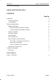
After Sales Cable Junction Box JBH–1 Technical Documentation CABLE JUNCTION BOX JBH–1 CONTENTS Page No Introduction 5 Technical Summary 5 List of Modules 5 Technical Specifications Modes of Operation 6 6 Phone Located Inside MBH–9 Holder 6 Phone Located Outside MBH–9 Holder 6 Extreme Conditions 6 Maximum Ratings 6 Control Signals 6 AC Characteristics 6 External Signals and Connections 6 HFJ Cable + Connector (Connector A) 7 Phone Connector X001 7 Coax Coil Cord Mini RF Connector
Cable Junction Box JBH–1 After Sales Technical Documentation [This page intentionally left blank] Page 4 Original, 05/94
After Sales Cable Junction Box JBH–1 Technical Documentation Introduction The JBH–1 Cable Junction Box has been designed for use specifically with the MBH–9 In–car Holder (to which it interfaces) and the existing Fixed Car Kit (based on the HFJ–2 Handsfree Junction Box ) The JBH–1 enables the signals from the Coax Coil Cord, which plugs into the Phone, to be split into audio and RF for connection to the HFJ–2 Handsfree Junction Box (via the SCE–2 Front Mount Cable if the Booster is fitted) and the Vehicl
Cable Junction Box JBH–1 After Sales Technical Documentation Technical Specifications Modes of Operation Phone Located Inside MBH–9 Holder Phone operates in “Handsfree” mode and connected to external antenna. Phone is charged by HFJ–2 through JBH–1. Phone Located Outside MBH–9 Holder Phone operates in “Handset” mode and connected to external antenna. Phone is charged by HFJ–2 through JBH–1.
After Sales Cable Junction Box JBH–1 Technical Documentation HFJ Cable + Connector (Connector A) Signal Name Pin/Con Notes XEXAUD/TXI 1 Booster Control.
Cable Junction Box JBH–1 After Sales Technical Documentation Coax Coil Cord Mini RF Connector Signal Name Pin/Conn Notes RF Conductor Centre Pin RF Ground Shield RF Signal from phone to external Antenna RF Signal Ground Connection Mechanical Characteristics Unit JBH–1 Dimensions (mm) (WxHxD) 49x22x54 Weight (g) Cable Length (metres) Material/ Colour 150 Antenna:0.30 0.015 Audio: 1.45 0.
After Sales Cable Junction Box JBH–1 Technical Documentation Figure 1: Schematic Mini UHF Connector CONNECTOR A W001 BROWN E1 ORANGE E2 VIOLET E3 BLUE 8 8 X002_8 XEAR GREEN YELLOW YELLOW E8 RED BLACK X002_7 XMIC BLUE X1–3 HOOK R2 N/F X1–4 XEAR X1–5 DGND X1–6 VC E5 X1–7 MBUS RED 6 6 X002_6 AGND/ SGND 0R0 BROWN 3 3 X002_3 MBUS X1–2 XEXAUD R1 E4 2 2 X002_2 DGND/ PGND S1 GREEN 5 5 X002_5 HOOK X1–1 VC WHITE 1 1 X002_1 XEXAUD/ TXI X001 CONNECTOR B 4 4 X002_4 Vc Mini RF
Cable Junction Box JBH–1 After Sales Technical Documentation [This page intentionally left blank] Page 10 Original, 05/94