
User Guide


After Sales
Technical Documentation
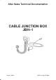
Cable Junction Box JBH–1
Original, 05/94 Page 5
Introduction
The JBH–1 Cable Junction Box has been designed for use specifically with
the MBH–9 In–car Holder (to which it interfaces) and the existing Fixed Car
Kit (based on the HFJ–2 Handsfree Junction Box )
The JBH–1 enables the signals from the Coax Coil Cord, which plugs into the
Phone, to be split into audio and RF for connection to the HFJ–2 Handsfree
Junction Box (via the SCE–2 Front Mount Cable if the Booster is fitted) and
the Vehicle Antenna (via the XRH–1 RF extension Cable if the Booster is
fitted).
The JBH–1 Cable Junction Box enables the phone to access all the normal
features of the existing HFJ–2 Handsfree Junction Box, with the exception of
an External Audio Handset which is NOT specified for use with this phone.
Technical Summary
The JBH–1 Cable Junction Box is a passive device and therefore connects
directly between the phone and HFJ–2/SCE–2 and the Vehicle
Antenna/XRH–1. However, there is a PCB (DC8) contained within the
Accessory Connector upon which there is mounted a Reed Switch and a zero
Ohm resistor to act as a link, since the same DCX2 PCB is used in another
application. The Reed Switch is “pulled” by a Magnet located in the MBH–9
In–car Holder; its function is to signal to the phone whether it is located in the
holder or not. If the phone is located in the holder then it will operate in
“Handsfree” mode, if not then it will operate in “Handset” mode. The Reed
Switch is of the “Normally Open” type ie. it is closed by the MBH–9 magnet.
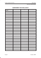
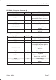
List of Modules
Name of Module Type Code Material Code Notes
Cable Junction Box JBH–1 0630008 Complete
Assembled Unit
Connector PCB
Module
DC8 0200377 Fits inside
accessory
connector
HFJ Cable +
Connectors
4C22080 7100422 NMP Cable used
on MCH–3
Assembly Parts MJBH1 0260336