
User Guide


After Sales
Technical Documentation
Cigarette Lighter Charger LCH–2
Original, 05/94 Page 7
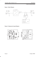
Pulse–width Control
Pulse width is controlled by comparator N110B, where the sawtooth
voltage from the oscillator is compared to a d.c. control voltage. Max.
control voltage is set by resistor divider R121/R120 to make sure that
pulse width cannot reach 100 % under any conditions as this would mean
short–circuiting VB to GND via V112.
When the control voltage drops, so do the pulse width and the converter
output current. The control voltage can be pulled down by output current
comparator N110C, output voltage comparator N110D, or by the ”error”
output pin of a reference regulator N100.
Current Limiting
Output current is measured with series resistor R116 connected between
L112 and GND. When the converter operates with the output loaded it
generates a negative voltage drop (as compared to GND) over this
resistor.
The voltage drop is added to the positive reference value set by R122 and
R123 and used as the current comparator positive input. The current
comparator compares the level of this input to zero (ground) level. When
the current reaches the limit, voltage at the positive input falls to zero and
the comparator output goes down, limiting the duty cycle. The value of the
current limit is set by resistor divider R122, R123. A negative feedback for
stabilizing the comparator is produced with R124.