
User Guide


After Sales
Technical Documentation
CARK30 Installation Guide
Original, 09/94 Page 7
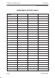
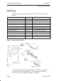
CARK30 Component Parts
Cable Junction Box (JBH–1) / In–car Holder (MBH–9)
This combination enables the phone to operate in handsfree mode. The
coil cord, from the cable junction box (JBH–1), plugs into the bottom of the
phone; the phone is then placed into the holder (MBH–9) which should be
mounted in a convenient dashboard location. When the phone is located
in the MBH–9 holder, it will operate in handsfree mode automatically. On
removing the phone from the holder, it reverts to normal handset
operation.
Mounting Plate and Swivel Mount (MKE–1 and HHS–1)
The mounting plate (MKE–1) and swivel mount (HHS–1) mounting
brackets are interchangeable. Either one can be used to mount both the
JBH–1 or the HFJ–2. The MKE–1 is a fixed position mount; HHS–1 is a
swivel mount which allows for adjustable mounting angles.
Cable Clip (CKH–1)
The cable clip (CKH–1) enables the coil cord from JBH–1 to be secured
when it is not connected to the phone.
HF Junction Box (HFJ–2)
The handsfree junction box (HFJ–2) provides and controls the supply
voltages for the accessories and the charge current for the phone. In
addition, it controls the audio paths to accessories and handsfree
equipment. The jack marked HANDSET/ACCESSORY is reserved for
optional accessories.
Power Cable (PCH–4)
The power cable connects to the handsfree junction box (HFJ–2) via the 4
pin connector. The red (+12V) and black (GND) wires must be connected
directly to the vehicle battery terminals via the supplied fused connectors.
The yellow (XCRM) wire is for car radio mute function and the blue (IGNS)
wire is for the ignition sense function. The XCRM line goes down to 0V
during a call. The maximum sink current is 250mA, (see CAR RADIO
MUTING). The IGNS line is connected to a +12V voltage source,
controlled by the car ignition key. The ignition sense can utilize voltages
up to 24V, (see IGNITION SENSE).