
User Guide


After Sales
Technical Documentation
Booster Kit BSH–1
Original, 09/94Page 10
Power Level Control Circuit
The pulse–width modulated control signal TXC is initially fed through a
CMOS buffer D300 before being converted into a d.c. voltage by an RC
filter network comprising R301, R302, C300 and C301. This analogue
signal is fed through rectifier diode V603, and then to the non–inverting
input of a comparator N300. A voltage proportional to the output power is
rectified from the directional coupler (V202) by biased Schottky diode
V201. The rectified voltage is fed through R309 to the inverting input of
the comparator N300. The output signal from this comparator adjusts the
primary stage supply voltage of power hybrid N200 until both inputs of the
comparator have equal voltage levels. This ensures the power control
loop maintains the output power precisely at the desired value.
Transmitter Enable Circuit
The booster receives the transmitter enable command from the incoming
RF signal, which is rectified by Schottky diode pair V200. The rectified
signal is fed to the non–inverting input of a comparator N300. The
inverting input of the comparator has a fixed reference voltage, +4 V, so
when the rectified signal is higher than the reference the output of the
comparator goes high and the transmitter is switched on by transistors
V600 and V601.
Power–off Circuit
The booster unit is also provided with a ’watchdog’ function, which turns
off all supply voltages when a malfunction is detected. Comparator N300
detects the incoming RF signal and comparator N300 detects the output
signal of the booster. Both comparator output signals are fed through
voltage dividers to an EXOR time delay (approx 3s) circuit comprising
R511, C606 gate D300. The D300 output signal is fed via comparator
N400, which forms output TXI which in turn is fed to HFJ.
If TXI goes low, the HJF executes power off, i.e. removes VC. This, in
turn makes mains switch V218 non–conductive ensuring all supply
voltages disappear. When VC is removed, V219 becomes
non–conductive, which in turn makes V501 conduct. V501 discharges
C606 so that restarting the booster is possible when VC is reapplied.
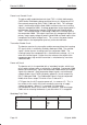
Watchdog Truth Table
Input Detector Output Detector Status TXI
1
0
1
0
1
1
0
0
OK
Error
Error
OK
1
0
0
1