
User Guide


After Sales
Technical Documentation
Booster Kit BSH–1
Original, 09/94 Page 5
Introduction
General
The Booster Kit comprises the following main items: Booster BSH–1;
Mounting Bracket MBM–3; Front Cable SCE–2; Extension Cable SCE–3;
and RF Extension Cable XRH–1. The Booster Kit upgrades the signal
output level of the phone to that of a full–powered mobile ie approx. 3W.
Note that only the Booster unit is covered in this booklet; the three cables
and the mounting bracket are included under non–serviceable
accessories.
Technical Specifications
Modes of Operation
With power off, only the VBAT supply (+12 V) is available; the VBAT
supply feeds the final amplifier stage.
With power on, mains switch (V218) is conducting, all voltages (+12 V, +8
V, +5 V) are on.
With the transmitter on, all voltages are on and the RF level is detected
from an input sense circuit, hence the TX control voltage to the power
amplifier primary stage is also switched on.
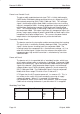
External Signals and Connections
X100 (RF_in) RF connector in
X101 (RF_out) RF connector out
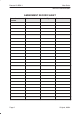
X500 to Junction Box (D25)
Pin Name Description
1 HOOK OUT Hook line from hook–switch
3, 17 GND Supply ground (–)
4, 16 +VBAT Supply voltage from vehicle battery (+)
6 VC HFJ supply voltage to HP, used to carry
”power_on” command to booster
11 TXI/SCL EEPROM clock line in startup, transmitter error
line
18 HOOK/SDA EEPROM data line from HFJ box startup, hook
line to HFJ.
23 TXC Pulse Width Modulated (PWM) power level
control from phone to booster.
24 SGND Signal ground to HFJ box.