After Sales Technical Documentation DESKTOP CHARGER CHH–6 Original, 11/94 NMP Part No.
After Sales Desktop Charger CHH–6 Technical Documentation AMENDMENT RECORD SHEET Amendment Number Page 2 Date Inserted By Comments Original, 11/94
After Sales Desktop Charger CHH–6 Technical Documentation DESKTOP CHARGER CHH–6 CONTENTS Page No Introduction 5 Technical Summary 5 Operation 5 Charging Indication 5 List of Modules 6 Basic Specifications 6 Technical Specifications Modes of Operation 6 6 Charge States and Charge Control 6 Charge Indication to User 7 DC Characteristics 8 AC Characteristics 8 Extreme Conditions 8 External Signals and Connections 8 Mechanical Characteristics 9 Environmental Conditions 10 Temper
Desktop Charger CHH–6 After Sales Technical Documentation List of Figures Figure 1: Block Diagram 14 Figure 2: Component Location Diagram 15 Figure 3: Exploded View 16 Figure 4: Circuit Diagram 21 Page 4 Original, 11/94
After Sales Desktop Charger CHH–6 Technical Documentation Introduction The CHH–6 Desktop Charger is designed to charge the phone and a spare battery; the battery can be any Ni–Cd or Ni–Mh type. In a standard configuration, rapid charging is possible by connecting the desktop charger to an ac power outlet via Rapid Charger, ACH–4. The rapid charger is connected to the phone via a dc connector located at the base of the phone.
After Sales Desktop Charger CHH–6 Technical Documentation Left Desktop Charger LED (for Spare Battery): The Red LED indicates that the battery is not fully charged due to one of the following conditions: either the battery or the phone is being charged at the rapid rate or charging is disabled due to the battery temperature being out of the normal operating range. The Green LED indicates that the battery is fully charged. A flashing RED LED indicates that a discharge cycle has been activated.
After Sales Desktop Charger CHH–6 Technical Documentation When the transistor is off, no current is supplied to the phone and the charger is in the constant voltage mode. In rapid charge mode, the phone turns the transistor on almost continuously. Having been charged in the rapid charge mode, the battery is kept fully charged using pulsed charging, i.e. switching power alternately on and off at a variable low duty cycle and a frequency of a few hertz.
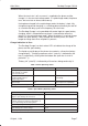
After Sales Desktop Charger CHH–6 Technical Documentation DC Characteristics Table 5. Supply Voltages and Power Consumption PARAMETERS TYPICAL / NOMINAL Output voltage: 12.0 +/– 1 V at 0 to 800 mA output current Output constant current: 750 +/– 70 mA within 5.0 to 10.0 V output voltage range Discharge current: 135 mA 30 mA nominal at 5V Discharge end voltage: 5 V (1 V / cell) 4% Operating input voltage: 12 Vdc 1V Max. input current: 800mA 70mA AC Characteristics Table 6.
After Sales Desktop Charger CHH–6 Technical Documentation Table 8. Rapid Charger AC Adapter Connector X130 SIGNAL NAME PIN / CONN. NOTES VDC 1 supply voltage input GND 2 common ground Table 9. Phone Charging Connectors X110, X111 SIGNAL NAME PIN / CONN. NOTES VC X110 charge voltage output PDET/GND X111 charge detect input / phone common ground Table 10.
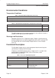
After Sales Desktop Charger CHH–6 Technical Documentation Environmental Conditions Temperature Conditions Table 11. Allowed Ambient Temperature (functional) ENVIRONMENTAL PARAMETER VALUE Low air temperature + 5°C High air temperature +45°C Table 12.
After Sales Desktop Charger CHH–6 Technical Documentation Table 13. Processor Input/Output Signals: (continued) SIGNAL NAME PA5/DISW NOTES Discharge control output, ”1”: discharge enabled PC6/BSW Spare battery charge control ”0”: charge disabled ”1”: rapid charge PWM: pulsed mode PC7 Watchdog reset output Table 14.
Desktop Charger CHH–6 After Sales Technical Documentation Circuit Description Charging the Spare Battery Charging current for the spare battery is fed via switching transistor V130 and Schottky diode V131. The transistor is controlled by the processor (BSW line). When the transistor is on, a constant current is supplied to the battery. This is the rapid charging mode. In the pulsed charging mode, charging current is adjusted by pulsing the rapid charge current.
After Sales Desktop Charger CHH–6 Technical Documentation Watchdog Circuit The processor generates positive pulses to output PC7 (pin 18). These pulses are received by transistor V160 and discharging capacitor C161. The capacitor is charged through resistor R163. This voltage is fed to regulator N100 shutdown input (pin 3) through transistor V162. If the processor stops, the voltage across the capacitor increases and the regulator is switched off.
After Sales Desktop Charger CHH–6 Technical Documentation Figure 1: Block Diagram " % " " # ! ! # # " " " " # # $ # !
After Sales Desktop Charger CHH–6 Technical Documentation Figure 2: Component Location Diagram Original, 11/94 Page 15
After Sales Desktop Charger CHH–6 Technical Documentation Assembly Figure 3: Exploded View 1 2 8 4 C1 5 3 7 3X Page 16 6 4X Original, 11/94
After Sales Desktop Charger CHH–6 Technical Documentation Assembly Parts ITEM QTY CODE DESCRIPTION VALUE 1 1 9460089 Discharge Button 4D22992 2 1 9450325 Front Cover D11317 3 1 9380488 Approval Label BABT A12455 4 1 9460088 Light Guide 3D22993 5 1 9450323 Bottom Cover D11318 6 1 6501067 Adhesive Foot D8.0 H2.
After Sales Desktop Charger CHH–6 Technical Documentation R148 R149 R150 R151 R152 R153 R154 R155 R156 R157 R158 R160 R161 R162 R163 R164 R170 R171 R172 R181 R182 R183 R184 R185 R186 R187 R188 R192 R193 R194 C102 C103 C104 C105 C130 C131 C132 C133 C134 C135 C136 C137 Page 18 1413603 1414029 1414029 1413635 1413924 1413924 1414029 1414029 1414029 1414029 1412729 1413603 1412430 1413924 1414244 1414244 1414533 1414477 1413603 1415576 1415576 1415576 1415576 1415576 1415576 1415576 1415576 1416040 1411490
After Sales Desktop Charger CHH–6 Technical Documentation C140 C141 C142 C143 C150 C151 C152 C153 C154 C155 C160 C161 C170 B150 V114 V129 V130 V131 V132 V134 V140 V141 V152 V153 V154 V155 V160 V162 V170 V181 V182 V183 V184 V185 D001 N100 N140 S130 X110 X111 X120 X121 2307816 2307816 2307816 2307816 2307816 2310343 2310343 2604209 2307816 2310738 2307816 2604209 2307816 4500822 4110074 4110074 4210112 4110074 4200917 4200226 4100567 4106992 4200917 4200917 4200917 4200917 4200917 4200917 4100567 4864378
Desktop Charger CHH–6 After Sales Technical Documentation X122 X123 X130 Page 20 9510170 Batt.conn.spring a11316 chh–6 9510170 Batt.conn.spring a11316 chh–6 5407088 DC connector d4.5/3.