
User Guide


After Sales
Technical Documentation
System Module
THX–4
Amendment 10/97Page 4–6
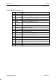
System Connector J1
Pin Name Description
1 VC Charger Input +ve
2 XEXAUD Booster power control output.
3 HOOK On hook indication for auxillary handset.
4 XEAR External earphone signal.
5 0V 0V for both charger and audio.
6 VC Charger input +ve
7 MBUS Bidirectional asynchronous data bus.
8 0V 0V for both charger and audio
9 XMIC External microphone signal
10 0V 0V for both charger and audio
11 0V For charger
12 VC Charger input +ve
13 VC Charger input +ve
14 0V 0V for charger
15 0V 0V
16 RF RF signal to duplex filter
17 RF RF signal to antenna
18 0V 0V
19 VBAT Battery voltage
20 BTEMP Battery temperature measurement, 27k pull–up
resistor to 4.8V.
21 BSI Battery size indication, 100k pull–up resistor to
+4.8V
22 0V 0V for battery