DNT2Mi-fp Data Network Terminal User manual C33999.
DNT2Mi-fp Data Network Terminal User manual The information in this documentation is subject to change without notice and describes only the product defined in the introduction of this documentation. This documentation is intended for the use of Nokia's customers only for the purposes of the agreement under which the documentation is submitted, and no part of it may be reproduced or transmitted in any form or means without the prior written permission of Nokia.
Contents Contents 3 Summary of changes 5 1 About this document 7 2 Introduction to DNT2Mi-fp 9 3 Front view 11 4 4.1 4.2 4.3 Rear panel 13 Line interface 14 Power supply 14 Terminal interface 21 5 Management 23 6 6.1 6.2 6.3 6.4 6.5 6.6 Commissioning 27 Management 28 Timing source 28 Line settings 29 Port settings 30 Protection settings 30 Measurements 31 7 7.1 7.2 7.3 7.
DNT2Mi-fp Data Network Terminal User manual 4 (60) © Nokia Corporation Nokia Proprietary and Confidential DN0445814 Issue 2-0 en
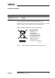
Summary of changes Document Date DN0445814 issue 2–0 en Aug 2005 DN0445814 Issue 1–0 en Mar 2004 Comment Product collection and disposal within the European Union Guidelines for product collection and safe disposal of the equipment are indicated with a sticker placed on the equipment, shown in the figure below. Product collection and disposal within European Union Do not dispose the product as unsorted municipal waste.
DNT2Mi-fp Data Network Terminal User manual 6 (60) © Nokia Corporation Nokia Proprietary and Confidential DN0445814 Issue 2-0 en
About this document 1 About this document This manual introduces the DNT2Mi-fp network terminal and provides information needed for its installation and use. This manual is intended for those who use DNT2Mi-fp as a network terminal. If you use it in a ACL2i-DNT2Mi-fp connection, refer to the ACL2i User Manual, which contains descriptions of the ACL2i, its functions and Q1 menus.
DNT2Mi-fp Data Network Terminal User manual 8 (60) © Nokia Corporation Nokia Proprietary and Confidential DN0445814 Issue 2-0 en
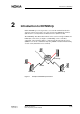
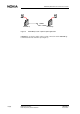
Introduction to DNT2Mi-fp 2 Introduction to DNT2Mi-fp Nokia DNT2Mi-fp is a fixed port data access network terminal intended for customer premises. It provides a two-wire or four-wire SHDSL line interface (ITU-T G.991.2) and symmetrical 2M data interface (ITU-T G.704). The DNT2Mi-fp Data Network Terminal can be used for example for BTS and PABX (E1) connections (see Figure 2). DNT2Mi-fp can be controlled, configured, and tested using Nokia’s common network management system (NMS).
DNT2Mi-fp Data Network Terminal User manual BTS BTS SHDSL DNT2Mi-fp Figure 3.
Front view 3 Front view Figure 4 presents DNT2Mi-fp front view with LED indicators. Power LED DSL LED Alarm LED Figure 4. Front view of DNT2Mi-fp When power is switched on, the unit performs an automatic self test, which is used to check the most vital operational functions of the equipment. After the test, the device is ready for use. During the power-up test, the LEDs are lit in the following sequence: 1. All 3 LEDs are lit for 10 seconds. 2.
DNT2Mi-fp Data Network Terminal User manual • If there is no line signal, the DSL LED is off. • If line is handshaking, the DSL LED is blinking. • If the line is up and running, the DSL LED is lit. The yellow Alarm LED indicates alarm situation. • If there is no alarm situation, the LED is off. • The Alarm LED is lit for instance if: • • no line signal or handshaking is ongoing or too high bit error ration (BER). no E1 data signal or framing error or too high bit error ration (BER).
Rear panel 4 Rear panel Figure 5 shows connector locations on the rear panel of a DNT2Mi-fp. 48VDC Wall mounting fastener LMI Slots for wall mounting fastener DIP Switch G.704/2M Earthing connector DSL Line Figure 5.
DNT2Mi-fp Data Network Terminal User manual 4.1 Line interface 6-pin modular jack, RJ-11 DSL Line 1 - 6 Pin Line interface 1. 2. 3. 4. 5. 6. Line 1a Line 1b Not connected Not connected Line 2a (not in use in 2-w mode) *) Line 2b (not in use in 2-w mode) *) *) not connected in T65690.01 Figure 6. 4.2 Line interfaces of DNT2Mi-fp Power supply DNT2Mi-fp can be fed with either, 48VDC or remotely via ACL2i through the line.
R232 R235 DN0445814 Issue 2-0 en R237 R225 Figure 7.
DNT2Mi-fp Data Network Terminal User manual NR2 NR3 NR4 Remote Power Supply (default) NR2 NR3 NR4 48V DC Supply NR2 NR3 NR4 External AC/DC converter Supply Figure 8.
Rear panel 1 Torx 8 - screw 2 Motherboard 3 Shell Assembled state 1 2 3 Groove that supports the back plate (see detail) Removal instruction: 1. Remove torx-screw with specified tool 2. Pull back plate along with motherboard using reasonable force out of the shell 3. Note that the back plate is supported from its upper end to the shell Figure 9.
DNT2Mi-fp Data Network Terminal User manual Earthing bar DSL Line cable 2 1.0 mm wire Remote power supply 6-pin modular jack, RJ-11 DSL Line 1 - 6 Pin Line interface 1. 2. 3. 4. 5. 6. Line 1a Line 1b Not connected Not connected Line 2a (not in use in 2-w mode) *) Line 2b (not in use in 2-w mode) *) *) not connected in T65690.01 Figure 10.
Rear panel 48VDC Earthing bar 2 1.0 mm wire 6-pin modular jack, RJ-11 48VDC 1 Figure 11. DN0445814 Issue 2-0 en - Pin 48VDC interface 6 1. + 2. 3. N.C 4. 5. 6.
DNT2Mi-fp Data Network Terminal User manual 48VDC 110/230 V AC AC/DC converter Earthing bar 2 1.0 mm wire Figure 12.
Rear panel 4.3 Terminal interface G.704/2M 8-pin modular jack, RJ-45 G.704/2M 1 Figure 13. DN0445814 Issue 2-0 en - 8 Pin Data interface 1. TX (OUT) 2. 3. SHIELD 4. RX (IN) 5. 6. SHIELD 7. Not connected 8. Not connected Symmetrical G.
DNT2Mi-fp Data Network Terminal User manual 22 (60) © Nokia Corporation Nokia Proprietary and Confidential DN0445814 Issue 2-0 en
Management 5 Management The Local Management Interface (LMI) is located at the rear panel (see Figure 12). The interface is used to manage DNT2Mi-fp with Service Terminal (V.11) and Macro Service Terminal Emulator (typically V.28) running on a PC or with other Nokia management software.
DNT2Mi-fp Data Network Terminal User manual LMI Interface type selection LMI V.11 1 V.28 DIP Switch 1 Local management connector (RJ-45) - 1 1. 2. 3. 4. 5. 6. 7. 8. 8 V.28 107 (HiZ) 108 (IN) 109 (HiZ) SG 103 (IN) 104 (OUT) 105 ] 106 Figure 14. Local management connector Table 1. Management interface cables V.11 Tx b (OUT) Tx a (OUT) SG Rx b (IN) Rx a (IN) Code Name Connector type Length E64320.01 Management cable (PC –> DNT2Mi-fp) D9F/RJ45 3m E62731.
Management DIP-switch DNT2Mi-fp - - Tx Tx Rx Tx Rx Tx Rx Q1 management bus Rx DNT2Mi-fp DSL Line Q1 management through Line Figure 15. Q1 management bus Up to 32 DNT2Mi-fp units can be connected to the same Q1 bus of V.11-type via a local management interface.
DNT2Mi-fp Data Network Terminal User manual 26 (60) © Nokia Corporation Nokia Proprietary and Confidential DN0445814 Issue 2-0 en
Commissioning 6 Commissioning This chapter describes the most common items that need to be checked before DNT2Mi-fp is taken into use. DNT2Mi-fp is ready to operate after the power supply (AC/DC converter, DC or remote power) and port and line cables are connected. However, identifications and settings should be checked and, if required, statistics and error counter should be reset.
DNT2Mi-fp Data Network Terminal User manual If errors were found during the power-up test, more information on this can be found in the Self test menu (Q1: 5,4,0). 6.1 Management DNT2Mi-fp can be managed through the line connection or local management port LMI. The following items need to be checked: Q1 transmission speed (Q1: 6,1,1) The Q1 transmission speed needs to be set to match the system management speed. Q1 address (Q1: 6,1,2) The equipment needs a Q1 address to be visible in the NMS systems.
Commissioning DNT2Mi-fp can also be used as a network timing source using the unit's Internal timing circuits. DNT2Mi-fp can also be used as Transparent timing. This means that both E1 transmission directions are independent. 6.3 Line settings You have to check the following items: Line interface (Q1: 6,3,3) The line interface settings determine line SHDSL mode, connection rate and use of wires. Typically, DNT2Mi-fp is configured as STU-R, Rate Adaptive.
DNT2Mi-fp Data Network Terminal User manual Line alarms (Q1: 6,3,8 and 6,3,9) The BER alarm limit and alarm severity have to be checked. 6.4 Port settings You have to check the following items: Port framing (Q1: 6,4,1) Check that the 2M data interface settings are compatible with the equipment they are connected to. No frame (Q1: 6,4,1,1) Alternative if full 2M is needed and no framing is required. Port statistics is not available. Only UAT is calculated if there is no G.703 signal present at the port.
Commissioning Default password for DNT2Mi-fp protection is DNT2Mi, and it can change by menu option (Q1: 10,4,3). 6.6 Measurements After all the settings have been checked, it is recommended that you carry out a line quality and BER test. Note Before starting the BER test, reset all statistics and error counters. Read statistics and error counters after the BER test. Noise margins, Rx and Tx line levels, and attenuations (Q1: 7,1...4) Establish a link between two units.
DNT2Mi-fp Data Network Terminal User manual 32 (60) © Nokia Corporation Nokia Proprietary and Confidential DN0445814 Issue 2-0 en
Maintenance 7 Maintenance This chapter describes what general information and statistics you can get on the equipment to be monitored. It also deals with possible alarms and faults. You can access all this information using Q1 menus. The menus are described in figure 20 and onwards. 7.
DNT2Mi-fp Data Network Terminal User manual In this menu the name of the supervised unit, installation date and installer are changeable. To change these parameters select Modify: Q1 menu option 4,7,2,1 for name, 4,7,4,1,1 for date and 4,7,4,1,2 for installer. Note that the maximum lengths are 15 characters for date and name and 20 characters for installer. There are two dates for installation date, First and Last.
Maintenance SB 1, Port Code Severity Q1 message 0x15 B Loop to interface 0x32 AS Loss of incoming 2 M signal 0x42 B Ais 2 M 0x51 AS Loss of frame alignment 0x56 B CRC multiframe alignment lost 0x63 AS, A, B BER > 1 E-3 0x66 AS, A, B BER > 1 E-6 0xb3 B Far-end alarm Code Severity Q1 message 0x15 B Loop to interface 0x30 AS Loss of incoming signal 0x51 AS Loss of frame alignment 0x63 AS, A, B BER > 1 E-3 0x66 AS, A, B BER > 1 E-3 0xb0 B Far-end alarm 1 0xb3 B
DNT2Mi-fp Data Network Terminal User manual Q1 management Automatic controll Note Equipment tests Power up test Self test After power is switched on Self test (5.4) During self test management and line connection is disconnected. Line interface test Network test loop Loop to Line(5,3,2) See Figure “Network test loop” after this table. Data coming from the line is looped back to the line. Port interface test Local test loop Loop to Port(5,2,3) See Figure “Local test loop” after this table.
Maintenance 7.4 Checking measurements and statistics The parameters that can be viewed through the Q1 menus Measurement (main menu branch 7 and Statistics (main menu branch 8) are listed below. Measurements via Q1 • Noise margin • Rx level • Tx level • Line attenuation • Line voltage (remote-powered) Attenuation can be 0 to 41 dB. Monitoring a line Tx level Line 1 or 2: xx dBm xx = +7.5 to +14.5 dBm Rx level Line 1 or 2: xx dBm xx = +14.
DNT2Mi-fp Data Network Terminal User manual Table 2. Statistics values via Q1 Information Abbreviation and/or ratio Description Total time TT Time passed since the last reset. Unavailability time UAT (Rx, Tx) Time during which severely errored seconds have occurred. ES Number of errored seconds.
Technical specifications 8 Technical specifications Table 3. DNT2Mi-fp dimensions Width 56 mm Height 173 mm Depth 138 mm Weight 510g Table 4. Environmental and mechanical Storage ETSI ETS 300 019-2-1 class 1.2 Operation ETSI ETS 300 019-2-3 class 3.2 Transportation ETSI ETS 300 019-2-2 class 2.3 Table 5. Line interface (in accordance with ITU-T G.991.
DNT2Mi-fp Data Network Terminal User manual Table 6. 2 M data interface Interface type G.703 (2 Mbit/s) 120-ohm symmetrical Maximum allowed timing jitter at receiver timing According to ITU-T G.823 Maximum generated timing jitter at receiver timing According to ITU-T G.823 Frame structure According to ITU-T G.704 Relevant ETSI ONP standards ETS 300 246, ETS 300 247, ETS 300 418, ETS 300 419 Electrical characteristics According to ITU-T G.
Technical specifications Data lead-time (ACL2i to DNT2Mi-fp) ms 4.0 3.5 3.0 2.5 2.0 1.5 1.0 0.5 0.
DNT2Mi-fp Data Network Terminal User manual Figure 21. Max SHDSL reach with Remote Powering The values marked in bold means that remote powering is limiting maximum length. Table 7. DNT2Mi-fp power supply Power consumption DNT2Mi-fp 5,5 W 4 - wire mode 4,5 W 2 - wire mode Power supply (external AC/DC converter).
Technical specifications Table 7. DNT2Mi-fp power supply (Continued) Voltage 90 to 264 VAC Frequency 47 to 65 Hz DC power supply Voltage 48V (40V to 70V) Remote power supply Voltage 50 to 150 V on both pairs as generated through ACL2i at central site Start-up voltage Min. 90 VDC Table 8. Mean time between failure (MTBF) DNT2Mi-fp > 75 years Electromagnetic compatibility (EMC) of DNT2Mi-fp complies with the following specifications: Table 9.
DNT2Mi-fp Data Network Terminal User manual 44 (60) © Nokia Corporation Nokia Proprietary and Confidential DN0445814 Issue 2-0 en
Factory settings 9 Factory settings The factory default values can be recalled from the Q1 menu path 6,7. The default values are marked bold in Q1 menu chart. Note Recalling of factory settings can take up to 60 seconds. Table 11. Service settings Q1 speed: 4800 Q1 address: 2 Q1 via line: On Table 12. Line interface settings PSD symmetric 2 – wire STU – R Power backoff: On Table 13.
DNT2Mi-fp Data Network Terminal User manual Table 14.
Q1 menu diagrams Appendix A. Q1 menu diagrams General The Q1 Main menu level contains the following 11 menus, of which those available in DNT2Mi-fp are typed in boldface in the list below: 1. Fault display 2. Local alarm cancel 3. Reset local cancel 4. Identifications 5. Controls 6. Settings 7. Measurements 8. Statistics 9. Testing 10. User priviliges 11. Miscellaneous Factory settings are marked within brackets on the Q1 menus diagrams below.
DNT2Mi-fp Data Network Terminal User manual 4 5 1 Fault display 2 Local alarm cancel *) 3 Reset local cancel *) 4 Identifications 5 Controls 6 Settings 7 Measurements 8 Statistics 9 Testing *) 10 User privileges 11 Miscellaneous *) 6 7 8 *) not implemented Figure 22.
Q1 menu diagrams 4 DNT-fp Identifications: 0 Display 1 Eq type 2 Eq name 4 Installation info 5 HW version 6 SW version 7 Modify 8 Serial number 4,0 Identifications Equipment type: DNT2Mi-fp G.704 4w (T65690) Equipment name: DNT2Mi-fp Installation date: First:2004-20-02 Last:2004-20-02 Installed by: Installer HW: E65691.01 A SW: S65692.01 A0 Serial number: 4H04.... 4,1 DNT2Mi-fp(G.
DNT2Mi-fp Data Network Terminal User manual 4,7 Modify: 2 Eq name 4 Installation info 4,7,2 Eq name: 0 Display 1 Modify 4,7,2,1 4,7,4 Installation info: 0 Display 1 Modify 4,7,4,1 Modify: 1 Date 2 Installed by Give new eq name: Max 15 characters 4,7,4,1,1 Give new Installation date: yyyy-mm-dd 4,7,4,1,2 Give new Installer: Max 20 characters 4,8 Serial number: 4H04... Figure 24.
Q1 menu diagrams 5 DNT-fp controls: 0 Display 1 All test loops off 2 Port test loop 3 Line test loop 4 Self test 5,2 Port test loop: 0 Display 1 Port test loop off 2 Loop to Port 5,3 Line test loop: 0 Display 1 Line test loop off 2 Loop to Line 5,4 Self test: 0 Result of last ST 1 Start Self Test 5,4,1 Run Self test: 1 Yes 2 No Figure 25.
DNT2Mi-fp Data Network Terminal User manual The factory settings are marked within brackets. 6 DNT-fp settings: 0 Display 1 Service options 2 Timing source (Line) 3 Line settings 4 Port settings 7 Load factory settings 6,1 Service options: 0 Display 1 Q1 Speed (4800) 2 Q1 Address (2) 3 Q1 via line (On) 7 Test time out limit (10) 12 Temperature alarm limit (75C) 13 Temperature alarm severity (No alarm) 6,1,1 Q1 speed: 0 Display Set speed 600 ...
Q1 menu diagrams 6,1,3 Q1 via line: 0 Display 1 On 2 Off 6,1,7 Test time out limit: 0 Display 1 to 64999 min 65000 no limit 6,1,12 Temperarure alarm limit: 0 Display 1 50C 2 55C 3 60C 4 65C 5 70C 6 75C 7 80C 8 85C 9 90C 6,1,13 Temperarure alarm severity: 0 Display 1 No alarm 2 A-level alarm 3 B-level alarm 6,2 Timing source: 0 Display 1 Internal 2 Line 3 Port 4 Transparent 6,3 6,4 6,7 Figure 27.
DNT2Mi-fp Data Network Terminal User manual The factory settings are marked within brackets. 6,3 Line settings: psdS = Power spectral density mask, 0 Display Symmetric 3 Line interface (STU-R, 2w) 32 = Line rate, the value of n x 64k 6 Power backoff (On) 8 BER alarm limit (E-3) 9 BER alarm severity (B-level alarm) *) not in T65690.
Q1 menu diagrams 6,4 The factory settings are marked within brackets. Port settings: 0 Display 1 Framing format (No frame) 2 Sa bits usage 8 BER alarm limit (E-3) 9 BER alarm severity (B-level alarm) 6,4,1 Framing format: 0 Display 1 No frame 2 Basic frame 3 CRC multiframe 4 BF monitoring 5 CRC monitoring 6,4,2 Sa bits usage: 6,4,2,1..
DNT2Mi-fp Data Network Terminal User manual 7 DNT-fp measurements: 0 Display all 1 Noise margins 2 Rx levels 3 Tx levels 4 Attenuations 5 Supply voltage 6 Temperature NM = Noise margin At = Attenuation P = Pair *) Not in T65690.
Q1 menu diagrams 8 DNT-fp statistics: 1 Port statistics 2 Line statistics 3 System counters 99 Reset all statistics 8,1 Port statistics: 3 Relative values 4 Absolute values 5 Reset statistics 1) You can choose up to 100 15 min periods or up to 30 24h periods 8,1,3 Port stat relative: 1 15 min periods 2 24h periods 8,1,3,1..2 Give period 0 to 100: 1) (0=curr., 1=last, 2=prev., etc.) 8,1,3,1..
DNT2Mi-fp Data Network Terminal User manual 8,2 Line statistics: 1 Line status 3 Relative values 4 Absolute values 5 Reset statistics 1) You can choose up to 100 15 min periods or up to 30 24h periods *) Not in T65690.01 8,2,3 Line stat relative: 1 15 min periods 2 24h periods 8,2,3,1..2 Give period 0 to 100 (0=curr., 1=last, 2=prev., etc.) 8,2,3,1..
Q1 menu diagrams The factory settings are marked within brackets. 10 DNT-fp privileges: 1 Password for privileges 3 Cancel privileges 4 Setting parameters 10,1 Password for privileges: Give password 10,3 Privileges cancelled 10,4 Setting parameters: 1 Password time out (10) 2 Protections (No protection) 3 New password 10,4,1 Password time out: 0 Display 1..1000 min 10,4,2 Protections 0 Display 1 No protection 2 Password required 10,4,3 Give new password: 1...7 characters Figure 33.
DNT2Mi-fp Data Network Terminal User manual 60 (60) © Nokia Corporation Nokia Proprietary and Confidential DN0445814 Issue 2-0 en