LCD Projector User’s Manual NEC VT45 User’s Manual Printed in China 7N8P0881 VT_H1-4 1 Black 01.9.
LIMITED WARRANTY GARANZIA LIMITATA Except as specified below, the warranty that may be provided by the dealer covers all defects in material or workmanship in this product. The following are not covered by the warranty: 1. Any product on which the serial number has been defaced, modified or removed. 2. Damage, deterioration or malfunction resulting from; a.
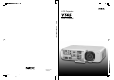
VT45 LCD Projector User’s Manual English E–1
IMPORTANT INFORMATION RF Interference Precautions Please read this manual carefully before using your NEC VT45 Projector and keep the manual handy for future reference. Your serial number is located under the name plate label on the right side of your VT45. Record it here: WARNING The Federal Communications Commission does not allow any modifications or changes to the unit EXCEPT those specified by NEC Technologies in this manual.
Important Safeguards CAUTION These safety instructions are to ensure the long life of your projector and to prevent fire and shock. Please read them carefully and heed all warnings. Installation 1. For best results, use your projector in a darkened room. 2. Place the projector on a flat, level surface in a dry area away from dust and moisture. 3. Do not place your projector in direct sunlight, near heaters or heat radiating appliances. 4.
Lamp Replacement • To replace the lamp, follow all instructions provided on page E-36. • Be sure to replace the lamp when the message "The lamp has reached the end of its usable life. Please replace the lamp." appears. If you continue to use the lamp after the lamp has reached the end of its usable life, the lamp bulb may shatter, and pieces of glass may be scattered in the lamp case. Do not touch them as the pieces of glass may cause injury. If this happens, contact your NEC dealer for lamp replacement.
TABLE OF CONTENTS Projector Options ................................................. E-32 Menu ............................................................... E-32 Menu Mode ................................................. E-32 Basic/Advanced .......................................... E-32 Language .................................................... E-32 Source Display ........................................... E-32 No Input Display .........................................
1. INTRODUCTION Introduction to the VT45 Projector • The supplied remote control can be used without a cable. • You can control the projector with a PC using the PC Control port. • The contemporary cabinet design is light, compact, easy to carry, and complements any office, boardroom or auditorium. This section introduces you to your new VT45 (SVGA) Projector and describes the features and controls.
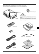
What's in the Box? Make sure your box contains everything listed. If any pieces are missing, contact your dealer. Please save the original box and packing materials if you ever need to ship your VT45 Projector.
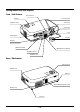
Getting to Know Your VT45 Projector Front / Side Features Remote Sensor Controls Lens Shift Lever Ventilation (outlet) Focus Ring ON STAN US STAT R WE PO UR SO CE D BY AU TO EN T ER JUST AD CT SELE ME CEL AN C NU Zoom Lever PC OL Lens CONTR RGB OUT OUT L/MONO IN IN RGB IN IN R IN Terminal Panel IN Lens Cap AC IN AC Input Connect the supplied power cable’s three-pin plug here.
Bottom / Side Features Lamp Cover Slot for Kensington MicroSaver Security System Lamp Cover Screw NOTE: Built-in Security Slot ( ) This security slot supports the MicroSaver® Security System. MicroSaver® is a registered trademark of Kensington Microware Inc.The logo is trademarked and owned by Kensington Microware Inc. Attaching the lens cap to the bottom with the supplied string and rivet 1. Thread the string through the hole on the lens cap and then tie a knot in the string.
Top Features 9 8 1 SO UR CE 4 AU TO ON ST AT US WE R ST AN D BY AD PO ST ME U N SE LE CT EN T ER 32 7 JU CANCE L 6 5 1. Power Button (ON / STAND BY) ( ) Use this button to turn the power on and off when the power is supplied and the projector is in standby mode. NOTE: To turn off the projector, press and hold this button for minimum of two seconds. 2.
Terminal Panel Features 7 4 5 2 8 AUDIO TUS STA ER BY ND POW STA ON IN RGB IN O ADJ R IN PC CONTROL AUT OUT RCE VIDEO IN L/MONO IN SOU RGB OUT S-VIDEO IN EN T ER UST T SELEC ME CEL AN C NU PC ROL CONT RGB OUT OUT O L/MON IN RGB IN IN IN R IN IN 6 3 1 AC IN 1. RGB Input Connector(Mini D-Sub 15 pin) Connect your PC or other RGB equipment. Use the supplied signal cable to connect to a PC. 6.
Remote Control Features Remote Control 1 1. Infrared Transmitter Direct the remote control toward the remote sensor on the projector cabinet. 2. Power Button If power is applied, you can use this button to turn your projector on and off. 2 RGB VIDEO S-VIDEO POWER 3 NOTE: To turn off the projector, press and hold the POWER button for a minimum of two seconds. 4 AUTO ADJ. MAGNIFY VOLUME 5 3. Source Buttons Press to select a video source. 7 8 4.
Operating Range Remote Control Battery Installation 1. Push to open the battery cover. 7m 22 feet 30˚ 30˚ 30˚ 30˚ 7m 22 feet 2. Remove both old batteries and install new ones (AA). Ensure that you have the batteries’ polarity (+/–) aligned correctly. 30˚ 30˚ 7m 22 feet 30˚ 7m 22 feet 30˚ 3. Put the battery cover back on. Do not mix different types of batteries or new and old batteries.
2. INSTALLATION This section describes how to set up your VT45 projector and how to connect video and audio sources. 5. To center the image vertically, lift the front edge of the projector and press the One-Touch Tilt button on the front side of the projector to release the Front Adjustable foot. Setting up Your Projector Side view Your VT45 Projector is simple to set up and use. But before you get started, you must first: 1. Determine the image size. 2.
Distance Chart Throw Distance Screen (inch) C Width Screen Center Lens Center/ Screen Bottom B α D 44.6 mm / 1.76” Screen Size (Diagonal) Height Projector feet B = Vertical distance between lens center and screen center C = Throw distance D = Vertical distance between lens center and bottom of screen for desktop α = Throw angle Lens Offset 5.
Ceiling Installation Projector feet Screen Bottom/ Lens Center D B 44.6 mm / 1.76” α Screen Center Throw Distance C B = Vertical distance between lens center and screen center C = Throw distance D = Vertical distance between lens center and top of screen α = Throw angle Lens Offset Diagonal inch mm 25 635 30 762 40 1016 60 1524 67 1702 72 1829 80 2032 84 2134 90 2286 100 2540 120 3048 150 3810 180 4572 200 5080 210 5334 240 6096 261 6629 270 6858 300 7620 5.
Wiring Diagram Macintosh or Compatibles (Desktop type or notebook type) Speaker System AUDIO S-VIDEO IN VIDEO IN RGB OUT L/MONO IN OUT R IN IN PC CONTROL RGB IN IBM VGA or Compatibles (Desktop type or notebook type) Signal cable (supplied) To mini D-Sub 15-pin connector on the projector. It is recommended that you use a commercially available distribution amplifier if connecting a signal cable longer than the supplied cable.
Connecting Your PC Signal cable (supplied) To mini D-Sub 15-pin connector on the projector. It is recommended that you use a commercially available distribution amplifier if connecting a signal cable longer than the supplied one.
Connecting Your Macintosh Computer Macintosh (Notebook type) CE L EN T ER ST JU AD ME E C R U SO TO AU S U BY AT ST ER D W AN PO ST N O N U T C LE E S CAN Signal cable (supplied) S-V IDE O IN AU VID EO IN DIO L /M IN ONO AU OU T R IN DIO RG BO U IN T CO PC NT RO L IN RG RG B IN BI N Audio cable (not supplied) Macintosh (Desktop type) NOTE: The new Macintosh computer such as G3 will have the 15 pin HD connector.
Connecting an External Monitor CE L EN T ER ME E C R U SO TO AU ST JU AD S U BY AT ST ER D W AN PO ST N O N U T C LE E S CAN S-V IDE O IN VID EO IN AU DIO AU DIO IN L /M IN ONO OU T R IN Audio cable (not supplied) RG BO UT RG BI N RG BO UT IN CO PC NTR OL RG B IN External monitor Signal cable (supplied) DIO AU You can connect a separate, external monitor to your VT45 to simultaneously view on a monitor the image you're projecting. To do so: 1.
Connecting Your DVD Player DVD player CE L S U BY AT ST ER D W AN PO ST N O N U T C LE E S EN T ER CAN Component video cable RCA 3 (not supplied) E C R U SO TO AU ST JU AD ME Cr Cb Red Y S-V L IDE O IN Blue R AU Green VID EO IN White DIO L /M IN ONO OU T Red R RG BO U IN T CO PC NT RO L IN RG RG Red B IN Blue BI N Red Green Blue Green Optional 15-pin-to-RCA (female) 3 cable (ADP-CV1) Audio Equipment Audio cable (not supplied) L R White Red You can connect your
Connecting Your VCR or Laser Disc Player CE L EN T ER U N ST JU AD ME E C R U SO TO AU S U BY AT ST ER D W AN PO ST N O T C LE E S CAN VCR/ Laser disc player S-V IDE O VID EO S-video cable (not supplied) S-V IDE O IN AU VID L EO IN DIO L /M IN ONO R OU R White N LI Red White T RG IN BO UT CO PC NT RO L IN DIO AU N RI DIO AU RG B IN Red Document camera Audio equipment VID EO L R White Red Video cable (not supplied) Audio cable (not supplied) Use common RCA cables
3.OPERATION This section describes how to select a computer or video source, how to adjust the picture, and how to customize the menu or projector settings. General Controls Before you turn on your projector, ensure that the computer or video source is turned on and that your lens cap is removed. 1. Turn on the Projector Plug the supplied power cable in the wall outlet and then press the main power switch. The projector will go into its standby mode and the power indicator will glow orange.
About Startup screen (Menu Language Select screen) When you first turn on the projector, you will get the Startup screen.This screen gives you the opportunity to select one of the seven menu languages: English, German, French, Itilan, Spanish, Swedish and Japanese. To select a menu language, follow these steps: 1. Use the or for the menu. buttons to select one of the seven languages Menu Language Select Please select a menu language. English Wählen Sie bitte die Menü Sprache aus.
Enlarging and Moving a Picture You can enlarge the area you want up to 400 percent. To do so: Adjust the image size up to 400 percent. MAGNIFY MAGNIFY Each of the feet height can be changed up to 1 mm or at angles up to 1 degree. While the picture is enlarged, you can move it using the “Select” , , , or button. Geometrical correction If the image is distorted or not displayed correctly on the screen, do the following. Use keystone correction for proper adjustment. See page E-29.
Using the Menus 1. Press the “Menu” button on the remote control or the projector cabinet to display the Menu. buttons on the remote control or the projector 2. Press the cabinet to highlight the menu for the item you want to adjust or set. 3. Press the button or the “Enter” button on the remote control or the projector cabinet to select a submenu or item. 4. Adjust the level or turn the selected item on or off by using “Select” or buttons on the remote control or the projector cabinet.
MENU Tree Basic/ Advanced Menu Sub Menu Basic Menu RGB Source Select Video Picture S-Video Volume Image Options Projector Options Picture Brightness 0 Contrast 0 Color 0 Source Select Hue 0 Picture Sharpness 0 Information Advanced Menu Volume Image Options Color Management Volume 0 Projector Options (Toutes) Information Items Normal/Eco 1/Eco 2 Keystone Factory Default Aspect Ratio Position/Clock Resolution Video Filter Gamma Correction All Data/Current Signal Lamp Mode Advan
Menu Elements Title bar Tab Setup Highlight Page1 Page2 Page3 Orientation Desktop Front Cinema Position Top Background Logo Page4 Solid triangle Slide ber Color Correction(User Adjust) Menu Menu mode Basic Color Tune 0 Language English Yellow 0 0 Source Display On Off Magenta No Input Display On Off Cyan Volume Bar On Off White Keystone Bar On Off Filter Clean Message On Off Menu Display Time Auto 45 Sec 0 On Off Radio button ○ ○ ○ ○ ○ ○ ○ ○ ○ ○ ○ ○ ○ ○ ○ ○ ○
Menu Descriptions & Functions Volume Adjusts the sound level of the projector. Source Select RGB Volume Video 0 S-Video Enables you to select a video source such as a VCR, DVD player, laser disc player, computer or document camera depending on what is connected to your inputs. Press the “Select” button on the projector cabinet or ▲▼ buttons on your remote control to highlight the menu for the item you want to adjust. NOTE:You can display the volume bar without opening the menu.
Aspect Ratio: Lamp Mode Aspect Ratio Lamp Mode Normal Eco1 Normal Eco2 This feature enables you to select three brightness modes of the lamp: Normal and Eco modes. The lamp life can be extended up to 2000 hours by using the Eco 2 mode. Normal Mode: This is the default setting. This setting consumes maximum current from the AC input and results in the most light output. Eco 1 Mode: Select this mode to extend the lamp life by up to 150%.
Position/ Clock (when Auto Adjust is off): Video Filter (when Auto Adjust is off): Position/Clock Horizontal Vertical Video Filter 100 Off Less More 50 Clock 800 Phase 50 This function reduces video noise. Off: The low-pass filter is not applied. Less: The low-pass filter is applied weakly. More: The low-pass filter is applied strongly. Screen adjustments are possible even when the filter is on.
Color Management White Balance (Advanced mode) Gamma Correction White Balance Color Correction Brightness Red 0 Brightness Green 0 Brightness Blue 0 Contrast Red 0 Contrast Green 0 Contrast Blue 0 White Balance Gamma Correction (Advanced mode) Gamma Correction Graphic Linear Black Enhance Use the or buttons to choose one mode from three options.
When this feature is turned on, the “No Input” message will appear if there is no signal present. Setup Enables you to set operating options. [Page1] This option turns on or off the volume bar when you adjust the sound volume using VOL+/-(up and down) button. On: You can increase or decrease the sound volume with the volume bar on screen. Page1 You can increase or decrease the level with the keystone bar on screen.
[Page 3] (Advanced mode) [Page 4] (Advanced mode) Setup Setup Page1 Page2 Page1 Off: Page3 Page4 Auto Adjust On Off Auto Start On Off Power Management On Off Communication Speed 19200bps Power Off Confirmation On Off Control Panel Key Lock Unlock Keystone Save On Off Clear Lamp Hour Meter Fan High Speed Mode On Off Clear Filter Usage Default Source Select Default Source When “Auto Adjust” is set to “On”, the projector automatically determines the best resolutio
To lock the cabinet buttons: 1) Use the Select or button to select “Control Panel Key Lock” and press the ENTER button. The submenu will be displayed. 2) Use the Select or button to select “Lock” and press the ENTER button. The following confirmation screen will be displayed. Lock Are you sure ? Information Displays the status of the current signal and lamp usage. This dialog box has three pages.
4. MAINTENANCE This section describes the simple maintenance procedures you should follow to replace the lamp, clean the filters, and replace the batteries in the remote control. 2. Loosen the two screws securing the lamp housing until the screwdriver goes into a freewheeling condition. The two screws are not removable. Replacing the Lamp Remove the lamp housing by pulling out the handle.
To replace the air-filter: 1. Remove the filter cover by pushing up on the catch of the cover until you feel it detach. U SE LE CT CANCEL ME N NOTE: When the lamp exceeds 1100 hours (up to 2100 hours in Eco 2 mode and up to 1600 hours in Eco 1 mode) of service, the projector cannot turn on and the menu is not displayed. If this happens, press the Help button on the remote control for a minimum of 10 seconds while in standby mode.
5. TROUBLESHOOTING This section helps you resolve problems you may encounter while setting up or using the projector.
6. SPECIFICATIONS This section provides technical information about the VT45 Projector’s performance. Model Number VT45 Optical LCD Panel 0.7” p-Si TFT active-matrix, 800 600 dots Lens Manual zoom, manual focus F2.0 – 2.2 Lamp f=26.7 – 29.3 mm 135W NSH lamp (120W in Eco 1 mode and 110W in Eco 2 mode) The lamp is warranted for 1000 hours of operation time within 6 months. Image Size 25 – 300 inches (0.64 – 7.62 m) diagonal Projection Distance 3.3 – 39.4 ft (1.0 – 11.
Cabinet Dimensions VT45 ON STAND BY POWER EL NC CA EN TE R STATUS SELECT SOURCE AUTO ADJUST 24 (0.94") 207(8.15") MENU 47(1.85") 117(4.61") RGB OUT OUT R IN IN PC CONTROL VT45 RGB IN AC IN 39.6 (1.56") 85(3.35") 90(3.54") VIDEO IN L/MONO IN 5(0.2") 4.6(0.18") 80(3.15") AUDIO S-VIDEO IN 5.4(0.21") 299(11.77") 4.6(0.18") 78(3.
D-Sub Pin Assignments Mini D-Sub 15 Pin Connector 5 4 3 2 1 10 9 8 7 6 15 14 13 12 11 Pin No. Signal Level Video signal : 0.
Timing Chart Signal # # # # # # # # # # # # # # # # # # # # # # # # # NTSC PAL SECAM VESA IBM MAC MAC MAC VESA VESA IBM VESA IBM VESA IBM IBM VESA VESA VESA VESA VESA MAC VESA VESA VESA IBM MAC VESA VESA VESA MAC SUN SGI VESA SGI VESA MAC MAC HP SUN VESA VESA HDTV (1080i)(1125i) HDTV (720p)(750p) SDTV (480p)(525p) SDTV (480i)(525i) Resolution ( Dots ) 768 640 640 640 640 640 640 640 640 640 720 720 720 720 800 800 800 800 800 832 1024 1024 1024 1024 1024 1024 1024 1152 1152 1152 1152 1280 1280 1280 1280
PC Control Codes Cable Connection Communication Protocol Baud rate: 19200 bps Function Code Data Data length: 8 bits POWER ON 02H 00H 00H 00H 00H 02H Parity: No parity POWER OFF 02H 01H 00H 00H 00H 03H Stop bit: One bit INPUT SELECT RGB 02H 03H 00H 00H 02H 01H 01H 09H X on/off: None Full duplex INPUT SELECT VIDEO 02H 03H 00H 00H 02H 01H 06H 0EH INPUT SELECT S-VIDEO 02H 03H 00H 00H 02H 01H 0BH 13H PICTURE MUTE ON 02H 10H 00H 00H 00H 12H PICTURE MUTE OFF 02H 11H 00H 00H 00H 13H SOUND