USERS GUIDE Version 1.0.
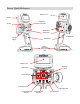
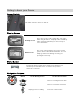
Sensor Quick Reference Display Screen Antenna Headphone & PC Connections Speaker On/Off Switch Steering Trim Steering W heel Throttle Trigger Shift Buttons Batter y Compartment / Receiver Program ming Cable Display Screen Navigation Controls Menu Button Selection Buttons (TL) Steering Trim (TR) Steering Trim (T1) Throttle Dual Rate Trim (T2) Steering Dual Rate Trim (T3) Throttle Trim
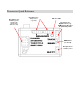
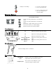
Transceiver Quick Reference Receptacle for: Receptacles for: RX Batter y (po wer) Steering (Ch1) Throttle (Ch2) Shift Servo (Ch3) Analog Sensor s (e.g., Temp) Indicator LED Receptacle for: Digital Sensor (e.g.
Sensor Quick Refer ence.................................. I I Tr ansceiver Quick Refer ence.........................I I I Statement of Complia nce ................................ 2 Getting t o k now your Sensor ........................... 3 Power Sw itch...................................................... 3 D isplay Screen .................................................... 3 M enu Button....................................................... 3 N avigation Buttons........................................
Statement of Compliance FCC Compliance St at ement This equipment has been tested and found to comply w ith the limit s for a Class B digit al dev ice, pursuant to Part 15 of the FCC Rules. These limits are designed to prov ide reasonable protection against harmful interference in a residential installat ion. This equipment generates, uses and can radiate radio frequency energy and, if not installed and used in accordance w ith the instructions, may cause harmful interference to radio communications.
Getting to know your Sensor Power Switch This sw itch turns the Sensor on and off. Display Screen Dr iving scr een This is the screen y ou’ll be seeing 95% of the tim e w hile using the Sensor. I t display s radio and battery status, telemetry data that y ou select, and your serv o information. Menu scr een This screen is the gatew ay to the Sensor’s menu sy stem, w hich is described in detail later. You can alw ay s go back to the driv ing screen by just pressing the menu k ey .
Display s next reading. OK • • I ncreases selected v alue. Goes to next sub-menu. • • Goes to selected sub-menu Sav es the change to the selected set ting. Selection Buttons I n the function menu Sets the currently edited v alue to its m aximum v alue. Sets the currently edited v alue to its m inimum v alue. Cancels any changes made and resets v alue to w here it w as before you started editing. Resets the v alue to the f actory default Trim Buttons T1 Adjusts the throttle dual rate set ting.
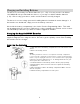
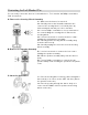
Charging and Installing Batteries The Sensor is pow ered by four AA-size batt eries (1.2~ 1.5V). You may use t he four AA-size 1.2V NiMH batt eries provided w it h t he Sensor, or you may use AA-size alkaline batt eries ( 1.5V) . Before using your Sensor, make sure the batt eries are fully charged. The Sensor is reverse volt age protected: inst alling batteries backw ards cannot damage it. If t he batteries are backw ards, simply reverse the batt ery connector.
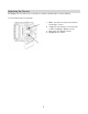
Adjusting the Screen The display screen at t he t op of t he Sensor can be reposit ioned for easier view ing. Tools needed: 7/64” hex w rench 1. Make sure Sensor is turned off before moving t he screen. 2. Using t he hex w rench, loosen t he two screw s holding t he display screen. 3. Reposit ion the display screen. 4.
Converting for Left Handed Use You can easily convert t he Sensor to left -handed use. Tools needed: # 2 Phillips screw driver, 7/ 64” hex w rench A: Remove t he St eering Wheel Assembly A1: Make sure the Sensor is t urned off A2. Carefully remove t he Nomadio emblem in the center of t he steering w heel. It is held in place by frict ion and pulls t ow ard you, it does not tw ist . A3. Use t he Phillips screwdriver to loosen and remove t he screw holding t he steering w heel. Remove t he st eering w heel.
D: Re-assemble D1. Reatt ach t he speaker t o t he plast ic cover using the two screw s. Be careful not to over t ight en and break t he speaker clamp. D2. Reconnect t he steering wheel w ire connector t o the st eering w heel. D3. Reatt ach t he speaker assembly to t he RIGHT side of t he Sensor body. D4. Reatt ach t he steering w heel assembly to t he LEFT side of t he Sensor body. D5. Reatt ach t he steering w heel. Make sure t he steering w heel has full left -and-right movement . D6.
Installing the Transceiver Mounting the Transceiver • • • • • • I nstall the transceiv er so it is protected from v ibration or shock . Use double-sided tape or Velcro® to mount the transceiv er. Position the transceiv er where it w ill not contact other solid components. Mount the transceiv er aw ay from mov ing parts, sharp corners, and possible contaminants (fuel, dirt, etc.).
Installing the Sensors Your Sensor radio system comes w it h several sensors t hat you can inst all in your vehicle and connect t o t he t ransceiver. W hen properly inst alled and connected, t hese sensors w ill send informat ion back t o the Sensor so that you can monitor t he readings while you drive. Receiver Battery Sensor The t ransceiver monit ors t he receiver battery volt age from t he POWER recept acle. There is no inst allat ion necessary for t his sensor.
Connect ion Connected Pins Connect ing the Temperat ure Sensor Unused Pin After you inst all t he t emperat ure sensor in t he vehicle, plug it into t he “Sensor 1” or “ Sensor 2” recept acle. The four-pin connector on t he sensor cable has only three w ires populated. The unpopulated pin should be the one furt hest from the connector key in t he receiver plast ic. The Sensor t ransceiver w ill aut omat ically detect which sensors are inst alled.
Binding the Transceiver The binding process “ locks” the Sensor and a t ransceiver t ogether so t hat t hey list en only t o each ot her. Since the Sensor has eight model memories, it is possible t hat your Sensor w ill be used to communicat e w it h eight t ransceivers. You must t herefore perform t he binding process once for each t ransceiver t hat w ill communicate w ith your Sensor.
Now , every t ime you t urn on the Sensor and set it t o the appropriate model ID ( see “ Managing Models” lat er in t his manual) , t he Sensor goes t o a special “ lookup channel” and searches for messages from t he appropriate VIN. W hen you t urn on the vehicle’s t ransceiver, the t ransceiver goes to t he lookup channel and broadcast s it s VIN so it can be found by the appropriat e Sensor. W hen t he Sensor finds the appropriat e VIN, t he connect ion is made.
Binding your transceiver the first time 1. Inst all a t ransceiver int o your vehicle. ( For t his example, inst all a t ransceiver int o your elect ric t ouring car, which w ill be know n t o t he Sensor as “ Model 1.”) 2. In t he Sensor’s “ Manage Models” funct ion menu, go t o “Act ive Model” and select t he appropriat e model ID for t he vehicle you are going to bind t o. ( For t his example, select “ Model 1.” ) 3.
Sensor Controls The funct ions of the Sensor are cont rolled through t he funct ion menu and/or t rim cont rols. To perform t his act ion… Toggles betw een the driv ing screen and the function menu or returns to the prev ious lev el from a submenu Menu: Go to the selected sub-menu Press… menu OK Menu: Mov e to the next higher menu item. Menu: Mov e to the next low er menu item. Menu: Go to the selected sub-menu. Driv e: Display next statistic. Menu: Decrease the selected v alue set ting.
Top Menu Level The follow ing illust rat ion show s t he funct ion menu st ructure for t he t op level menu. All main sub-menus may be accessed from t he t op menu level.
St eering Trim Steering t rim adjust s t he center point of t he steering servo by adjust ing the center point w it hin t he st eering servo’s t ot al t ravel range. Unlike steering subt rim, the steering left and right end point s are unaffect ed by steering t rim; by moving the center point of t he st eering servo using t rim, the center posit ion moves closer to one end point or t he ot her. Steering t rim should be used only after you have init ially adjust ed steering sub-t rim.
Adjust ing St eering Trim using t he Funct ion Menu Use t he navigat ion cont rols to adjust steering t rim as follow s: 1. Access the top function menu from the driv ing screen. menu 2. Nav igate to the Steer ing ( Ch1 ) menu. or 3. Nav igate to Tr im. or : then Value 0 4. Change the v alue. or -v e v alue (-100 Æ 1) + v e v alue (1 Æ 100) Descr iption Steering trim is centered w ithin the serv o range. Steering trim is to the LEFT. Steering trim is to the RI GHT.
St eering Dual Rat e Steering dual rat e adjust s the range of servo movement w hen t he st eering w heel is fully t urned in eit her t he left or right direct ion. This is used to increase or decrease the steering sensit ivit y across t he ent ire servo range. The steering dual rate value is applied to bot h left and right sides, and is expressed as a percent age of servo range (configured by end point adjust ment s) .
Adjust ing St eering Dual Rat e using the Trim Button You can also use t he T2 t rim butt on t o adjust the steering dual rat e. Dual Rat e and End Point Adjust ment Full servo range is det ermined by t he left and right end point adjust ment s. The dual rat e value determines the relat ive servo range between t he left and right end point s. The servo w ill never move beyond t he set end point adjust ment s, no matter w hat dual rat e sett ing is applied.
Adjust ing St eering Exponent ial Use t he navigat ion cont rols to adjust steering exponent ial as follow s: 1. Access the top function menu from the driv ing screen. menu 2. Nav igate to the Steer ing ( Ch1 ) menu. or 3. Nav igate to Expo. or : then Value 4. Change the v alue. or 0 -v e v alue (-1 to 100) + v e v alue (1 to 100) Descr iption Neutral steering response (linear). Milder steering response near center. Quick er steering response near center.
Adjust ing St eering Sub-t rim Use t he navigat ion cont rols to adjust steering sub-t rim as follow s: 1. Access the top function menu from the driv ing screen. menu 2. Nav igate to the Steer ing ( Ch1 ) menu. or 3. Nav igate to Sub Tr im. or : then Value 0 4. Change the v alue. or -v e v alue (-100 Æ 1) + v e v alue (1 Æ 100) Descr iption Steering sub-trim is centered w ithin the serv o range. Steering sub-trim is to the LEFT. Steering sub-trim is to the RI GHT.
Adjust ing St eering Trim I ncrem ent Use t he navigat ion cont rols to adjust steering t rim increment as follow s: 1. Access the top function menu from the driv ing screen. menu 2. Nav igate to the Steer ing ( Ch1 ) menu. or 3. Nav igate to Tr im I ncr ement . or : then Value or 4. Change the v alue. 1-20 Descr iption Steering trim v alue changes by set increment. Use sm aller v alues for finer trim control. Use larger v alues for coarser trim control.
St eering Left End Point The steering left end point value adjust s how far t he st eering servo t urns t o t he LEFT w it h respect t o it s full range of mot ion t o the left . End point adjust ment should be adjust ed prior t o ot her steering sett ings, as t he left end point value affect s ot her steering sett ings. The left end point is set independent ly of t he right end point (w hich adjust s how far t he st eering servo t urns t o t he RIGHT) .
Changing t he left end point value has t he follow ing visual effect on t he driving screen bars. Left end point v alue is approximately the same as the right end point v alue. I ncreased left end point v alue (more servo trav el to the left is possible). Decreased left end point v alue (less serv o trav el to the left is possible).
St eering Right End Point The steering right end point value adjust s how far t he st eering servo t urns t o the RIGHT w it h respect t o it s full range of mot ion t o the right. End point adjust ment should be adjusted prior t o ot her st eering sett ings, as t he right end point value affect s ot her st eering sett ings. The right end point is set independent ly of t he left end point (w hich adjust s how far t he steering servo t urns t o t he LEFT).
The posit ion of t he pointer on the bar is affected by t he steering end point values ( left and right) and t rim sett ing; increasing t he right end point value may visually appear t o have t he same effect as decreasing t he left end point value. Adjust ing t he Right End Point The right end point value is a relat ive value, and is expressed as the percent age of full t ravel t o t he right .
St eering Servo Reverse Steering servo reversing reverses t he direct ion t he servo moves upon receiving an input from the steering w heel. Changing t he St eering Servo Reverse Sett ing Use t he navigat ion cont rols to change t he st eering servo reverse sett ing as follow s: 1. Access the top function menu from the driv ing screen. menu 2. Nav igate to the Steer ing ( Ch1 ) menu. or 3. Nav igate to Ser vo Rever se . or : then Value 4. Change the v alue.
St eering Speed Steering speed allow s you to limit t he maximum speed t hat the steering servo w ill be driven to match your movement s on t he wheel. There are t hree parameters t hat can be adjusted to precisely set up your lim it ing. Trigger set s the minimum amount of cont rol input before the speed lim it er becomes act ive. At 0% , limit ing is alw ays act ive ( input is alw ays > = 0%) . At 50%, lim it ing is only act ive if t he wheel is t urned half w ay or more.
Throttle Functions The follow ing illust rat ion show s t he funct ion menu st ructure for t he t hrott le funct ions: Throttle ( Ch 2) Trim Dual Rate 0 - 100 Throttle Expo - 100 to 100 Brake Expo - 100 to 100 Sub Trim - 100 to 100 Trim Increment 1 - 20 DR Increment 1 - 20 Brake End Point 0 to 100 Throttle End Point 0 to 100 Servo Reverse Servo Type Servo Speed Thrott le Trim Thrott le t rim adjust s the rest ing ( centered) posit ion of t he t hrott le servo horn (elect ric or nit ro vehi
Throttle Trim Steering (Ch1) Throttle (Ch2) Shift (Ch3) On the driv ing screen, throttle trim is represented by the position of the pointer on the middle bar.
Thrott le Dual Rat e Thrott le dual rate adjust s the range of servo movement w hen t he thrott le t rigger is moved from full brake t o full t hrott le posit ion. This is used t o increase or decrease t he thrott le sensit ivit y across t he ent ire servo range. The thrott le dual rat e value is applied to bot h thrott le and brake end, and is expressed as a percent age of servo range ( configured by end point adjust ment s) .
Adjust ing Thrott le Dual Rat e using t he Funct ion Menu Use t he navigat ion cont rols to adjust t hrott le dual rat e as follow s: 1. Access the top function menu from the driv ing screen. menu 2. Nav igate to the Thr ottle ( Ch2) menu. or 3. Nav igate to Dual Rate . or : then Value 0 4. Change the v alue. or 1-99 100 Descr iption Throttle/ brak e range is set to minimum (0% ). Throttle/ brak e range is set to a percentage of full range. For example, v alue “50” giv es 50% of full serv o range.
Thrott le Exponent ial Thrott le exponent ial adjust s how quickly or slow ly t he t hrott le servo responds w it h respect to t he amount that t he thrott le t rigger is moved t o t he THROTTLE end. This affect s t he sensit ivit y of t he thrott le servo near it s neut ral posit ion. Adjust ing t he t hrott le exponent ial does not affect t he brake exponent ial; t hese sett ings are set individually.
Brake Exponent ial Brake exponent ial adjust s how quickly or slow ly t he t hrott le servo responds w it h respect to t he amount that t he thrott le t rigger is moved t o t he BRAKE end. This affect s t he sensit ivit y of t he t hrott le servo near it s neut ral posit ion. Adjust ing t he brake exponent ial does not affect t he t hrott le exponent ial; t hese sett ings are set individually.
Thrott le Sub-Trim Thrott le sub-t rim adjust s t he center point of t he t hrott le servo. This differs from t hrott le t rim in t hat thrott le sub-t rim adjust s the servo’s ent ire t ravel range; by moving t he center point of the servo, t he thrott le and brake end point s (t hrott le, brake) st ay the same relat ive “ dist ance” from the servo center.
Thrott le Trim I ncre ment Thrott le t rim increment adjust s t he sensit ivit y of the t hrott le t rim button, by adjust ing the amount that t he t hrott le t rim value changes for one “ st ep” of adjust ment . For example, sett ing t he t hrott le t rim increment value t o “ 5” changes the t hrott le t rim value by 5 each t ime t hat the thrott le t rim butt on is pressed once. Adjust ing Thrott le Trim I ncre ment Use t he navigat ion cont rols to adjust t hrott le t rim increment as follow s: 1.
Adjust ing Thrott le Dual Rat e I ncrement Use t he navigat ion cont rols to adjust t hrott le dual rat e increment as follow s: 1. Access the top function menu from the driv ing screen. menu 2. Nav igate to the Thr ottle ( Ch2) menu or 3. Nav igate to DR I ncr ement . or : then Value 4. Change the v alue. or 1-20 Descr iption Throttle dual rate v alue changes by set increment. Use sm aller v alues for finer dual rate control. Use larger v alues for coarser dual rate control.
On the driv ing screen, the brak e end point is represented by the length of the bar to the left of the pointer on the middle bar. Brake End Point Steering (Ch1) Throttle (Ch2) Shift (Ch3) The greater the left length of the bar, the greater the brak e end point v alue. The position of the pointer on the bar is affected by end point setti ngs ( thr ottle and br ak e) and tr im setting. Changing t he brake end point value has t he follow ing visual effect on t he driving screen bars.
Adjust ing t he Brake End Point The brake end point value is a relat ive value, and is expressed as t he percent age of full t ravel t o t he BRAKE end. For example, sett ing t he brake end point value t o “ 50” allow s t he t hrott le t o go to only 50% of full brake. Use t he navigat ion cont rols to adjust t he brake end point as follow s: 1. Access the top function menu from the driv ing screen. menu 2. Nav igate to the Thr ottle ( Ch2) menu. or 3. Nav igate to Br ak e End Point .
Thrott le End Point The thrott le end point value adjust s how far the t hrott le goes to t he THROTTLE end w it h respect t o it s full range of mot ion t o the t hrott le end. End point adjust ment should be adjust ed prior t o ot her t hrott le sett ings, as t he thrott le end point value affect s other t hrott le sett ings. The thrott le end point is set independent ly of t he brake end point (w hich adjust s how far t he thrott le servo t urns t o the BRAKE end) .
The posit ion of t he pointer on the bar is affected by end point values (t hrott le and brake) and t rim sett ing; increasing t he thrott le end point value may visually appear t o have t he same effect as decreasing t he brake end point value. Adjust ing t he Thrott le End Point The thrott le end point value is a relat ive value, and is expressed as t he percent age of full t ravel t o the THROTTLE end.
Changing t he Thrott le Servo Reverse Sett ing Use t he navigat ion cont rols to change t he t hrott le servo reverse sett ing as follow s: 1. Access the top function menu from the driv ing screen. menu 2. Nav igate to the Thr ottle ( Ch2) menu. or 3. Nav igate to Ser vo Rever se . or : then Value 4. Change the v alue. Off On or Descr iption Standard serv o direction. Rev ersed servo direction.
Thrott le Speed Thrott le speed allow s you to limit t he maximum speed t hat the thrott le servo w ill be driven t o match your movement s on t he t rigger. There are four paramet ers t hat can be adjusted to precisely set up your lim it ing. Thrott le Speed determines t he percent age of full speed t hat is applied t o the t hrott le movement s t hat are above the t hrott le t rigger sett ing. 100 is maximum servo movement rate. 1 is minimum rat e. Default is 100 ( full speed).
Changing t he Thrott le Speed Use t he navigat ion cont rols to change t he st eering servo t ype as follow s: 1. Access the top function menu from the driv ing screen. menu 2. Nav igate to the Steer ing ( Ch1 ) menu. or 3. Nav igate to Thr ottle Speed. or : then Value Throttle Speed 4. Change the v alues. or Brak e Speed Throttle Trigger Brak e Trigger Descr iption The amount of limiting applied to serv o throttle motion once the trigger amount has been exceeded.
Shift Servo Functions The follow ing illust rat ion show s t he funct ion menu st ructure for t he shift servo funct ions: Shift ( Ch 3) Trim Dual Rate - 100 to 100 0 - 100 Low End Point - 100 to 0 High End Point 0 to 100 Servo Reverse Off , On Servo Type Analog , Digital Mode Off , Toggle , Hold , 4 WS Ch3 Speed Thr/Brake Speed,Trigger Shift Servo Trim Shift servo t rim adjust s t he rest ing ( centered) posit ion of t he shift servo.
Adjust ing Shift Servo Trim Use t he navigat ion cont rols to adjust shift servo t rim as follow s: 1. Access the top function menu from the driv ing screen. menu 2. Nav igate to the Shift ( Ch3 ) menu. or 3. Nav igate to Tr im. or : then Value 0 4. Change the v alue. or -v e v alue (-100 Æ -1) + v e v alue (1 Æ 100) Descr iption Shift serv o trim is centered w ithin the serv o range. Shift serv o trim is to the LOW end. Shift serv o trim is to the HI GH end.
Changing t he dual rat e sett ing has the follow ing visual effect on t he driving screen bars: Full servo range is used. Low er dual rate v alue reduces serv o range. Adjust ing Shift Servo Dual Rat e Use t he navigat ion cont rols to adjust shift servo dual rat e as follow s: 1. Access the top function menu from the driv ing screen. menu 2. Nav igate to the Shift ( Ch3 ) menu. or 3. Nav igate to Dual Rate . or : then Value 0 4. Change the v alue.
On the driv ing screen, the low end point is represented by the length of the bar to the left of the pointer on the low er bar. Low End Point Steering (Ch1) Throttle (Ch2) The greater the left length of the bar, the greater the low end point v alue. Shift (Ch3) The position of the pointer on the bar is affected by end poi nt settings ( low and high) and tr im setting. Changing t he low end point value has the follow ing visual effect on the driving screen bars.
Trim and EPA I nt eract ion A trim (or sub-trim) setting of 100 is equiv alent to an End Point setting of 20. High End Point The shift servo high end point value adjust s t he shift servo’s ending posit ion after shift ing upw ards. This is int ended t o be high gear and goes w it h t he upshift sound event . The end point adjust ment s should be adjusted prior t o ot her sett ings.
The posit ion of t he point er on t he bar is affect ed by end point sett ings (low and high) and t rim sett ing; increasing t he high end point value may visually appear t o have the same effect as decreasing the low end point value. Adjust ing t he High End Point The high end point value is a relat ive value, and is expressed as t he percent age of full t ravel t o t he HIGH end.
Shift Servo Reverse Shift servo reversing reverses t he direct ion t he shift servo moves upon receiving an input from the grip buttons. Changing t he Shift Servo Reverse Sett ing Use t he navigat ion cont rols to change t he shift servo reverse sett ing as follow s: 1. Access the top function menu from the driv ing screen. menu 2. Nav igate to the Shift ( Ch3 ) menu. or 3. Nav igate to Ser vo Rever se . or : then Value 4. Change the v alue. or Off On Descr iption Standard serv o direction.
Changing t he Shift Servo Type Use t he navigat ion cont rols to change t he shift servo t ype as follow s: 1. Access the top function menu from the driv ing screen. menu 2. Nav igate to the Shift ( Ch3 ) menu. or 3. Nav igate to Ser vo Type . or 4. Change the v alue. : or then Value Descr iption Analog Shift serv o is analog. Digital Shift serv o is digital. Shift Servo Mode Shift servo mode cont rols the operat ion of t he shift funct ion.
Note that in 4W S or Thr/ Brake mode the sett ings on t his screen (End Point s, Dual Rate, Trim, Reverse, Type, and Servo Speed) st ill t ake effect . The Expo sett ing from t he mast er channel is used, for Thr/ Brake Aut o St art, Idle Up, and ABS apply. Ch3 Speed Ch3 speed allow s you t o limit t he maximum speed t hat t he shift servo w ill be driven t o mat ch your movement s on t he butt on. There are four parameters that can be adjust ed t o precisely set up your limit ing.
Changing t he Ch3 Speed Use t he navigat ion cont rols to change t he st eering servo t ype as follow s: 1. Access the top function menu from the driv ing screen. menu 2. Nav igate to the Steer ing ( Ch1 ) menu. or 3. Nav igate to Thr ottle Speed. or : then Value 4. Change the v alues. or Descr iption Return/ Brak e Speed The amount of limiting applied to serv o throttle motion once the trigger amount has been exceeded.
Model Management The follow ing illust rat ion show s t he funct ion menu st ructure for t he model management funct ions: Manage Models Active Model New Model Delete Model Copy Model Rebind Act ive Model The Sensor can st ore all sett ings for up to eight vehicles. The Act ive Model funct ion is used to select t he model to be used. W hen binding w it h a t ransceiver in a vehicle, you must first select t he act ive model t o ident ify t he vehicle.
New Model You can create a new model sett ings profile if t here are any model memories remaining. Creat ing a new model allow s you t o store t he sett ings for anot her model. By default , the new model sett ing is given the number of the next highest model number ( For example, if t here are current ly 4 model sett ings, creat ing a new model w ill creat e “ Model 5” and make it the default model.) You can change t he model name from your PC using t he Digit al RC Deskt op.
Delet ing a Model Use t he navigat ion cont rols to delete a model as follow s: 1. Access the top function menu from the driv ing screen. menu 2. Nav igate to the Manage Models menu. or 3. Nav igate to Active Model. or 4. Nav igate to the model y ou w ant to delete. or 5. Nav igate to and activ ate Delete Model. or 6. At the confirmation screen: • Select Yes to delete the activ e model. • Select No to cancel the operation. or 7. Confirm y our selection.
Rebinding You can rebind t o the t ransceiver in a specific model ( ident ified by a model profile) . Rebinding to a Model Use t he cont rols to rebind to a model as follow s: 1. Access the top function menu from the driv ing screen. menu 2. Nav igate to the Manage Models menu. or 3. Nav igate to Active Model. or 4. Nav igate to the model y ou w ant to rebind w ith. or 5. Nav igate to and activ ate Rebind. or : then : then 6.
Controller Setup The follow ing illust rat ion show s t he funct ion menu st ructure for t he cont roller set up funct ions: Controller Setup Audio Volume Vibrator 0 - 11 Off, On Backlight 0- 10 Contrast 0- 10 Calibrate Audio Volume You can set the audio volume t o one of eleven set t ings. W hile many RC cont rollers let you adjust t he sound t o just t en sett ings, Sensor gives you one more. It ’s one louder.
Vibrat or As you might guess, t his opt ion let s you t urn t he vibrat ion opt ion on and off. Turning t he Vibrat or On/ Off Use t he navigat ion cont rols to t urn the vibrat or on/off as follow s: 1. Access the top function menu from the driv ing screen. menu 2. Nav igate to the Contr oller Setup menu. or 3. Nav igate to Vibr ator . or 4. Turn the v ibration option on/off. or : then Back light You can set the bright ness of t he display screen backlight .
Adjust ing t he Display Backlight Level Use t he navigat ion cont rols to adjust t he display backlight level as follow s: 1. Access the top function menu from the driv ing screen. menu 2. Nav igate to the Contr oller Setup menu. or 3. Nav igate to Back light . or 4. Adjust the display screen back light lev el. : then or Value Descr iption 0 - 10 0 turns back light off. (Maximum battery life) 10 is the brightest back light lev el.
Calibrat e You can recalibrat e t he Sensor st eering and t hrott le cont rols. This does not change any of t he steering or t hrott le sett ings t hat are st ored in t he memory profile. Recalibrat ing t he Sensor Use t he navigat ion cont rols to recalibrat e t he Sensor as follow s: 1. Access the top function menu from the driv ing screen. menu 2. Nav igate to the Contr oller Setup menu. or : then 3. Nav igate to and activ ate Calibr ate . or : then 4.
Failsafes You can set up the failsafe posit ions of t he servos so t hat in t he event of loss of signal, the servos go t o t heir set failsafe posit ions. Default failsafe posit ions are centered st eering and t rim. Sett ing Failsafe Modes Use t he navigat ion cont rols to set the failsafe modes as follow s: 1. Access the top function menu from the driv ing screen. 2. Nav igate to the Advanced menu. 3. Nav igate to the Failsafe menu. 4. Nav igate to Steer ing.
Sett ing Failsafe Posit ions Use t he navigat ion cont rols to set the failsafe posit ions as follow s: 1. Access the top function menu from the driv ing screen. menu 2. Nav igate to the Advanced menu. or : then 3. Nav igate to the Failsafe menu. or : then 4. Nav igate to Set Failsafes. or 5. At the confirmation screen: • Select Yes to capture the serv o failsafe set tings. • Select No to abandon the operation. or 6. Confirm y our selection. OK 7.
Sensor Digital RC Desktop The innovat ive Sensor Digit al RC Deskt op can be used t o program t he funct ionalit y of your Sensor using your comput er. The supplied adapt or cable is used to connect your Sensor t o an availab le USB port on your computer, allow ing your Sensor and t he RC Deskt op t o communicate and exchange informat ion. The RC Deskt op interface has t he same menu st ruct ure as that cont ained w it hin your Sensor; and has been designed t o be very easy t o use.
3. W hen t he inst allat ion begins you w ill be presented w it h a Setup W izard that begins w it h t he Nomadio License Agreement . Click I Agree t o cont inue.
4. Next choose the dest inat ion folder for the Digit al RC Desktop by eit her t yping in t he path or clicking t he Brow se button and picking the folder you w ish to use. Click the Next butt on t o cont inue. 5. At t he next screen, select t he St art Menu folder for t he Digit al RC Deskt op’s short cut s. Click t he Do not creat e short cut s checkbox if you do not w ant shortcut s created. Click I nst all t o cont inue t he Set up W izard.
6. The Setup W izard w ill next inst all all of t he files required. 7. After inst alling t he required files, the Set up W izard w ill inst all t he Universal Serial Bus device drivers that w ill allow t he Digit al RC Deskt op t o communicate w it h t he Sensor.
8. You w ill t hen be show n t he License Agreement for t he device drivers. Choose I accept t he t erms of t he license agreement and t hen click Ne xt t o cont inue. 9. On W indow s XP you w ill be prompt ed if you w ant t o inst all each of t he tw o device drivers. Nomadio is act ively w orking t ow ards achieving W indow s Logo Cert ificat ion and current ly passes all t he required t est s available from W indow s Hardw are Qualit y Labs. Click Cont inue Anyw ay t o cont inue t he inst allat ion.
10. Once the device drivers are inst alled, click Finish t o complete t he device driver setup. 11. Digit al RC Deskt op Set up is now almost done. Click Ne xt t o cont inue.
12. Leave the Run Nomadio Digit al RC Deskt op now? checkbox select ed for t he Set up W izard to launch the program after exit ing t he Set up W izard. Click Finish t o exit t he Nomadio Digit al RC Deskt op Setup.
Connecting the Sensor to your Computer To connect your Sensor t o your comput er, do t he follow ing: 1. Plug t he small end of the supplied adaptor cable int o t he recept acle on t he left side of t he Sensor. 2. Plug t he other end of t he cable into an availab le USB port on your computer. Your computer w ill recognize t he Sensor as being connected via a new serial communicat ions port.
Registration 1. W hen you st art t he Digit al RC Deskt op t he first t ime, you w ill be prompted to regist er. Click Yes t o cont inue. If you click No , you can regist er you w ill be prompted again the next t ime you st art t he Digit al RC Deskt op. You can register immediat ely by choosing t he Help menu and t hen choosing Regist er new Sensor. 2. The Digit al RC Deskt op w ill now read your Sensor’s ID. Connect and turn on your Sensor and click OK.
3. Your web brow ser w ill t hen be opened to a web page t hat w ill ask you for regist rat ion informat ion. Your Sensor ID w ill be aut omat ically read from your Sensor and filled in. 4. W hen you click the Regist er button, a confirmat ion e-mail w ill be sent t o you. This w ill e-mail w ill cont ain a link back to Nomadio’s regist rat ion site w here you w ill be able to get your regist rat ion code.
5. Ent er your regist rat ion code in the Digit al RC Desktop and click t he OK button. If you press Cancel, you can ent er your regist rat ion code by choosing t he Help menu and choosing Ent er Regist rat ion Code. 6. You are now registered. Receiving Settings From the Sensor The Digit al RC Deskt op w ill at tempt to receive sett ings from t he Sensor on st art up. You can also choose t he File menu and t hen choose Receive Sett ings from Sensor.
Editing Settings Simply use the sett ings menu on t he left side of t he screen t o find t he sett ings you w ish t o edit . Individual sett ings appear in the right side of the screen. Changes can be saved t o a file on your PC and/ or sent to t he Sensor. Saving Settings Sett ings can be saved by choosing t he File menu and choosing eit her Save or Save As… . Choosing Save saves the sett ings t o t he current file name. Choosing Save As… let s you pick a file name.
Sending Settings to the Sensor You can send your sett ings t o t he Sensor by choosing the File menu and t hen choosing Send Sett ings to Sensor. You can also send your sett ings by choosing t he Send Sett ings to Sensor toolbar butt on. If you forget to send your sett ings to t he sensor aft er edit ing t hem, t he Digit al RC Desktop w ill prompt you t o send your sett ings on exit .
Specifications * Specif icat ions subject t o change wit hout not ice. Sensor Controller Radio Type: digital spread spectrum 2.4Ghz Radio Mode: direct sequence spread spectrum Range: 1000ft.
Support Nomadio is committ ed t o providing t he best support in t he RC market for it s product s. If you have any issues w it h your Sensor, please visit our support website at http:/ / support.nomadio.net There you w ill f ind a wealt h of know ledge from ot her Sensor users as well as Nomadio’s support st aff. Should you need to cont act Nomadio direct ly web support st aff w ill give you t he informat ion necessary t o get you running.
Nomadio 3 Year Limited Warranty Warranty Coverage Nomadio's w arranty obligations are limited to the terms set forth below: Nomadio, as defined below , w arrants this Nomadio-branded hardw are product against defects in materials and w ork manship under normal use for a period of THREE (3) YEARS from the date of retail purchase by the original end-user purchaser ("W arranty Period").
EXCEPT AS PROVIDED IN THIS WARRANTY AND TO THE EXTENT PERMITTED BY LAW , NOMADIO IS NOT RESPONSI BLE FOR DI RECT, SPECIAL, INCI DENTAL OR CONSEQUENTIAL DAMAGES RESULTI NG FROM ANY BREACH OF WARRANTY OR CONDITION, OR UNDER ANY OTHER LEGAL THEORY, I NCLUDING BUT NOT LI MI TED TO LOSS OF USE; LOSS OF REVENUE; LOSS OF ACTUAL OR ANTICIPATED PROFITS (INCLUDI NG LOSS OF PROFI TS ON CONTRACTS); LOSS OF THE USE OF MONEY; LOSS OF ANTICIPATED SAVI NGS; LOSS OF BUSINESS; LOSS OF OPPORTUNI TY; LOSS OF GOODW I LL; LOSS O