USERS GUIDE Version 2.
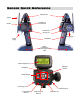
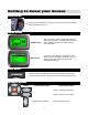
Sensor Quick Reference Display Screen Antenna Headphone & PC Connections Speaker On/Off Switch Steering Trim Steering Wheel Throttle Trigger Shift Buttons Battery Compartment / Receiver Programming Cable Graphic Display Screen Navigation Controls Menu Button Selection Buttons (TL) Steering Trim (TR) Steering Trim (T1) Throttle Dual Rate Trim (T2) Steering Dual Rate Trim (T3) Throttle Trim
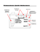
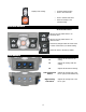
Transceiver Quick Reference Receptacle for: Receptacles for: RX Battery (power) Steering (Ch1) Throttle (Ch2) Shift Servo (Ch3) Analog Sensors (e.g., Temp) Indicator LED Receptacle for: Digital Sensor (e.g.
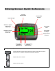
Driving Screen Quick Reference Currently Displayed Stat Signal Strength Statistics: Highest value seen of current stat. Current Model Number Current Stat Value Statistics: Lowest value seen of current stat.
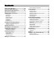
Contents Sensor Quick Reference .................................II Transceiver Quick Reference ....................... III Driving Screen Quick Reference ................... IV Statement of Compliance................................1 Getting to know your Sensor ..........................3 Power Switch .......................................................... 3 Display Screen......................................................... 3 Menu Button ...........................................................
Statement of Compliance FCC Compliance Statement This equipment has been tested and found to comply with the limits for a Class B digital device, pursuant to Part 15 of the FCC Rules. These limits are designed to provide reasonable protection against harmful interference in a residential installation. This equipment generates, uses and can radiate radio frequency energy and, if not installed and used in accordance with the instructions, may cause harmful interference to radio communications.
Modular Approval Statement If you install the Sensor transceiver inside of a vehicle, and you are not the final end user, FCC regulations require you to make the Sensor transceiver’s FCC ID easily visible to the end user.
Getting to know your Sensor Power Switch This switch turns the Sensor on and off. It is recessed to prevent accidental switching during travel or use. Display Screen Driving screen Menu screen This is the screen you’ll be seeing 95% of the time while using the Sensor. It displays radio and battery status, telemetry data that you select, and your servo information. This screen is the gateway to the Sensor’s menu system, which is described in detail later.
Displays next reading. • • Increases selected value. Goes to next sub-menu. • • Goes to selected sub-menu Saves the change to the selected setting. Selection Buttons In the function menu Sets the currently edited value to its maximum value. Sets the currently edited value to its minimum value. Cancels any changes made and resets value to where it was before you started editing. Resets the value to the factory default Trim Buttons T1 Adjusts the throttle dual rate setting.
Grip Buttons Performs shifting action on channel 3. Connection Connection Ports Headphone port Computer port Accepts a 1/8” stereo headphone jack. The output is the same in each ear (mono). This connects to the USB port of your computer using the supplied cable.
Charging and Installing Batteries The Sensor is powered by four AA-size batteries (1.2~1.5V). You may use the four AA-size 1.2V NiMH batteries provided with the Sensor, or you may use AA-size alkaline batteries (1.5V). Before using your Sensor, make sure the batteries are fully charged. The Sensor is reverse voltage protected: installing batteries backwards cannot damage it. If the batteries are backwards, simply reverse the battery connector.
Adjusting the Screen The display screen at the top of the Sensor can be repositioned for easier viewing. Tools needed: 7/64” hex wrench 1. Make sure Sensor is turned off before moving the screen. 2. Using the hex wrench, loosen the two screws holding the display screen. 3. Reposition the display screen. 4.
Converting for Left Handed Use You can easily convert the Sensor to left-handed use. Tools needed: #2 Phillips screwdriver, 7/64” hex wrench A: Remove the Steering Wheel Assembly A1: Make sure the Sensor is turned off A2. Carefully remove the Nomadio emblem in the center of the steering wheel. It is held in place by friction and pulls toward you, it does not twist. A3. Use the Phillips screwdriver to loosen and remove the screw holding the steering wheel. Remove the steering wheel. A4.
C: Swap the Assemblies D: Re-assemble C1. Pass the steering wheel connector wire through the Sensor body so it comes out the LEFT side hole (where the speaker used to be). C2. Pass the speaker connector wire through the Sensor body so it comes out the RIGHT side hole (where the steering wheel used to be). D1. Reconnect the speaker wire to the speaker assembly. Be careful not to over tighten and break the speaker clamp. D2. Reconnect the steering wheel wire connector to the steering wheel. D3.
Installing the Transceiver Mounting the Transceiver • • • • • • Install the transceiver so it is protected from vibration or shock. Use double-sided tape or Velcro® to mount the transceiver. Position the transceiver where it will not contact other solid components. Mount the transceiver away from moving parts, sharp corners, and possible contaminants (fuel, dirt, etc.). When possible, waterproof and protect the transceiver by wrapping it in foam rubber and placing it in a rubber balloon or plastic bag.
FCC Compliance Reminder If you install the Sensor transceiver inside of a vehicle, and you are not the final end user, FCC regulations require you to make the Sensor Transceiver’s FCC ID easily visible to the end user. See the FCC Compliance section for more information: Installing the Sensors Your Sensor radio system comes with several sensors that you can install in your vehicle and connect to the transceiver.
When installing on a nitro motor, place the sensor as low as possible on the head, opposite the exhaust port. The sensor may also be installed on an electric motor, battery pack, or ESC heat sink. Connection Connected Pins Connecting the Temperature Sensor Unused Pin After you install the temperature sensor in the vehicle, plug it into the “Sensor 1” or “Sensor 2” receptacle. The four-pin connector on the sensor cable has only three wires populated.
Tachometer Sensor The tachometer (“tach”) sensor is used to monitor the rotation speed of a vehicle component such as a driveshaft and this speed is converted into vehicle speed. You will need to measure the distance your model rolls in order to provide the Sensor with enough information to give you an accurate speed. We recommend that you get a tape measure and measure several rotations of the wheel to reduce the measurement error. Installation 1.
• The sensor side of the tach circuit board must be mounted closest to magnets. The sensor is on the opposite side from the large chip that protrudes from the shrink tubing. The graphic above shows where the sensor is so you can mount it correctly. • When moving, the magnets should pass directly over the center of the sensor. • We have used a variety of methods of mounting tach sensors, depending on the car and the chosen location.
Binding the Transceiver The binding process “locks” the Sensor and a transceiver together so that they listen only to each other. Since the Sensor has forty model memories, it is possible that your Sensor will be used to communicate with as many as forty transceivers. You must therefore perform the binding process once for each transceiver that will communicate with your Sensor.
Now, every time you turn on the Sensor and set it to the appropriate model ID (see “Managing Models” later in this manual), the Sensor goes to a special “lookup channel” and searches for messages from the appropriate VIN. When you turn on the vehicle’s transceiver, the transceiver goes to the lookup channel and broadcasts its VIN so it can be found by the appropriate Sensor. When the Sensor finds the appropriate VIN, the connection is made.
Binding your transceiver the first time 1. Install a transceiver into your vehicle. (For this example, install a transceiver into your electric touring car, which will be known to the Sensor as “Model 1.”) 2. In the Sensor’s “Manage Models” function menu, go to “Active Model” and select the appropriate model ID for the vehicle you are going to bind to. (For this example, select “Model 1.”) 3. After putting your model on a stand to prevent runaways, power up the vehicle and transceiver. 4.
Sensor Controls The functions of the Sensor are controlled through the function menu and/or trim controls. To perform this action… Press… Toggles between the driving screen and the function menu or returns to the previous level from a submenu Menu: Go to the selected sub-menu Menu: Move to the next higher menu item. Menu: Move to the next lower menu item. Menu: Go to the selected sub-menu. Drive: Display next statistic. Menu: Decrease the selected value setting. Drive: Display previous statistic.
Top Menu Level The following illustration shows the function menu structure for the top level menu. All main sub-menus may be accessed from the top menu level. Channels 3 & 4 have identical setups, and are documented together.
Steering Trim Steering trim adjusts the center point of the steering servo by adjusting the center point within the steering servo’s total travel range. Unlike steering sub-trim, the steering left and right end points are unaffected by steering trim; by moving the center point of the steering servo using trim, the center position moves closer to one end point or the other. Steering trim should be used only after you have initially adjusted steering sub-trim.
Adjusting Steering Trim using the Function Menu Use the navigation controls to adjust steering trim as follows: 1. Access the top function menu from the driving screen. menu 2. Navigate to the Steering (Ch1) menu. or 3. Navigate to Trim. or : then Value 0 4. Change the value. or -ve value (-100 Æ 1) +ve value (1 Æ 100) Description Steering trim is centered within the servo range. Steering trim is to the LEFT. Steering trim is to the RIGHT.
Steering Dual Rate Steering dual rate adjusts the range of servo movement when the steering wheel is fully turned in either the left or right direction. This is used to increase or decrease the steering sensitivity across the entire servo range. The steering dual rate value is applied to both left and right sides, and is expressed as a percentage of servo range (configured by end point adjustments).
Adjusting Steering Dual Rate using the Trim Button You can also use the T2 trim button to adjust the steering dual rate. Dual Rate and End Point Adjustment Full servo range is determined by the left and right end point adjustments. The dual rate value determines the relative servo range between the left and right end points. The servo will never move beyond the set end point adjustments, no matter what dual rate setting is applied.
Servo travel RIGHT 1~100% (quick) +ve exponential (quicker response) 0% ( linear) Steering wheel turned full LEFT Neutral Steering wheel tur ned full RIGHT A positive (+ve) exponential value gives a quicker steering response near the steering neutral point, making it MORE responsive to steering inputs at the steering wheel. Servo travel LEFT Adjusting Steering Exponential Use the navigation controls to adjust steering exponential as follows: 1. Access the top function menu from the driving screen.
Adjusting Steering Sub-trim Use the navigation controls to adjust steering sub-trim as follows: 1. Access the top function menu from the driving screen. menu 2. Navigate to the Steering (Ch1) menu. or 3. Navigate to Sub Trim. or : then Value 0 4. Change the value. -ve value (-100 Æ 1) +ve value (1 Æ 100) or Description Steering sub-trim is centered within the servo range. Steering sub-trim is to the LEFT. Steering sub-trim is to the RIGHT.
Steering Dual Rate Increment Steering dual rate increment adjusts the sensitivity of the steering dual rate by adjusting the amount dual rate value increments for one “step” of adjustment. For example, setting the dual rate increment value to “5” changes the steering dual rate value by 5 each time that a steering dual rate trim button is pressed once. Adjusting Steering Dual Rate Increment Use the navigation controls to adjust steering dual rate increment as follows: 1.
Left End Point Steering (Ch1) Throttle (Ch2) Shift (Ch3) Ch4 On the driving screen, the left end point is represented by the length of the bar to the left of the pointer on the upper bar. The greater the left length of the bar, the greater the left end point value. The position of the pointer on the bar is affected by the end point settings (left and right) and trim settings. Changing the left end point value has the following visual effect on the driving screen bars.
Use the navigation controls to adjust the left end point as follows: 1. Access the top function menu from the driving screen. menu 2. Navigate to the Steering (Ch1) menu. or 3. Navigate to Left End Point. or : then Value 0 4. Change the value. or 1-99 100 Description Minimum left end point; allows NO turning motion to the left. Left end point value is set to a percentage of full left-turning range. For example, a value of “50” gives 50% of full left-turning range.
Right End Point Steering (Ch1) Throttle (Ch2) Shift (Ch3) Ch4 On the driving screen, the right end point is represented by the length of the bar to the right of the pointer on the upper bar. The greater the right length of the bar, the greater the right end point value. The position of the pointer on the bar is affected by the end point values (left and right) and trim setting. Changing the right end point value has the following visual effect on the driving screen bars.
Use the navigation controls to adjust the right end point as follows: 1. Access the top function menu from the driving screen. menu 2. Navigate to the Steering (Ch1) menu. or 3. Navigate to Right End Point. or : then Value 0 4. Change the value. or 1-99 100 Description Minimum right end point; allows NO turning motion to the right. Right end point setting is set to a percentage of full right-turning range. For example, a value of “50” gives 50% of full right-turning range.
Steering Servo Type Steering servo type lets you select the type of steering servo (analog or digital) in the vehicle. Analog servos are sent signals at 50 frames/sec, while Digital servos are sent signals at 100 frames/sec. If you have high end analog servos, they may operate better with the digital setting, try both settings and choose the best performance. Changing the Steering Servo Type Use the navigation controls to change the steering servo type as follows: 1.
Changing the Steering Speed Use the navigation controls to change the steering servo type as follows: 1. Access the top function menu from the driving screen. menu 2. Navigate to the Steering (Ch1) menu. or 3. Navigate to Steering Speed. or : then Value 4. Change the values. Input Speed or Return Speed Trigger Description The percentage of full speed applied to servo motion away from center once the trigger amount has been exceeded.
Throttle Functions The following illustration shows the function menu structure for the throttle functions: Throttle (Ch 2) Trim Dual Rate 0 - 100 Throttle Expo -100 to 100 Brake Expo -100 to 100 Sub Trim -100 to 100 Trim Increment 1 - 20 DR Increment 1 - 20 Brake End Point 0 to 100 Throttle End Point 0 to 100 Servo Reverse Servo Type Servo Speed Throttle Trim Throttle trim adjusts the resting (centered) position of the throttle servo horn (electric or nitro vehicle) or the neutral point o
Throttle Trim Steering (Ch1) Throttle (Ch2) Shift (Ch3) Ch4 On the driving screen, throttle trim is represented by the position of the pointer on the middle bar.
Throttle Dual Rate Throttle dual rate adjusts the range of servo movement when the throttle trigger is moved from full brake to full throttle position. This is used to increase or decrease the throttle sensitivity across the entire servo range. The throttle dual rate value is applied to both throttle and brake end, and is expressed as a percentage of servo range (configured by end point adjustments).
Adjusting Throttle Dual Rate using the Function Menu Use the navigation controls to adjust throttle dual rate as follows: 1. Access the top function menu from the driving screen. menu 2. Navigate to the Throttle (Ch2) menu. or 3. Navigate to Dual Rate. or : then Value 0 4. Change the value. or 1-99 100 Description Throttle/brake range is set to minimum (0%). Throttle/brake range is set to a percentage of full range. For example, value “50” gives 50% of full servo range.
Ser vo travel THROTTLE 0% (linear) -1 ~ -100% (mild) Neutral A negative (-ve) exponential value gives a milder throttle response near the throttle neutral point, making it LESS responsive to braking inputs at the throttle trigger. F ull throttle -ve exponential (milder response) Ser vo travel THROTTLE 1~100% ( quick) A positive (+ve) exponential value gives a quicker throttle response near the throttle neutral point, making it MORE responsive to braking inputs at the throttle trigger.
Brake Exponential Brake exponential adjusts how quickly or slowly the throttle servo responds with respect to the amount that the throttle trigger is moved to the BRAKE end. This affects the sensitivity of the throttle servo near its neutral position. Adjusting the brake exponential does not affect the throttle exponential; these settings are set individually.
Throttle Sub-Trim Throttle sub-trim adjusts the center point of the throttle servo. This differs from throttle trim in that throttle sub-trim adjusts the servo’s entire travel range; by moving the center point of the servo, the throttle and brake end points (throttle, brake) stay the same relative “distance” from the servo center. Throttle sub-trim should be initially adjusted before using throttle trim, which is used to make fine adjustments to center the throttle within the total steering range.
Throttle Trim Increment Throttle trim increment adjusts the sensitivity of the throttle trim button, by adjusting the amount that the throttle trim value changes for one “step” of adjustment. For example, setting the throttle trim increment value to “5” changes the throttle trim value by 5 each time that the throttle trim button is pressed once. Adjusting Throttle Trim Increment Use the navigation controls to adjust throttle trim increment as follows: 1.
Adjusting Throttle Dual Rate Increment Use the navigation controls to adjust throttle dual rate increment as follows: 1. Access the top function menu from the driving screen. menu 2. Navigate to the Throttle (Ch2) menu or 3. Navigate to DR Increment. or : then Value 4. Change the value. or 1-20 Description Throttle dual rate value changes by set increment. Use smaller values for finer dual rate control. Use larger values for coarser dual rate control.
Brake End Point Steering (Ch1) Throttle (Ch2) Shift (Ch3) Ch4 On the driving screen, the brake end point is represented by the length of the bar to the left of the pointer on the middle bar. The greater the left length of the bar, the greater the brake end point value. The position of the pointer on the bar is affected by end point settings (throttle and brake) and trim setting. Changing the brake end point value has the following visual effect on the driving screen bars.
Adjusting the Brake End Point The brake end point value is a relative value, and is expressed as the percentage of full travel to the BRAKE end. For example, setting the brake end point value to “50” allows the throttle to go to only 50% of full brake. Use the navigation controls to adjust the brake end point as follows: 1. Access the top function menu from the driving screen. menu 2. Navigate to the Throttle (Ch2) menu. or 3. Navigate to Brake End Point. or : then Value 0 4. Change the value.
Throttle End Point The throttle end point value adjusts how far the throttle goes to the THROTTLE end with respect to its full range of motion to the throttle end. End point adjustment should be adjusted prior to other throttle settings, as the throttle end point value affects other throttle settings. The throttle end point is set independently of the brake end point (which adjusts how far the throttle servo turns to the BRAKE end).
Throttle end point value is approximately the same as the brake end point value. Increased throttle end point value (more servo travel for THROTTLE is possible). Decreased throttle end point value (less servo travel for THROTTLE is possible). The position of the pointer on the bar is affected by end point values (throttle and brake) and trim setting; increasing the throttle end point value may visually appear to have the same effect as decreasing the brake end point value.
Throttle Servo Reverse Throttle servo reversing reverses the direction the throttle servo moves upon receiving an input from the throttle trigger. Changing the Throttle Servo Reverse Setting Use the navigation controls to change the throttle servo reverse setting as follows: 1. Access the top function menu from the driving screen. menu 2. Navigate to the Throttle (Ch2) menu. or 3. Navigate to Servo Reverse. or : then Value 4. Change the value. Off On or Description Standard servo direction.
Changing the Throttle Servo Type Use the navigation controls to change the throttle servo type as follows: 1. Access the top function menu from the driving screen. menu 2. Navigate to the Throttle (Ch2) menu. or 3. Navigate to Servo Type. or 4. Change the value. or : then Value Description Analog Digital Throttle servo is analog. Throttle servo is digital.
Changing the Throttle Speed Use the navigation controls to change the steering servo type as follows: 1. Access the top function menu from the driving screen. menu 2. Navigate to the Steering (Ch1) menu. or 3. Navigate to Throttle Speed. or : then Value 4. Change the values. Throttle Speed or Brake Speed Throttle Trigger Brake Trigger Description The amount of limiting applied to servo throttle motion once the trigger amount has been exceeded.
Channel 3 and Channel 4 Servo Functions Each of these servos can be used as a number of auxiliary functions such as shifting or acting as a second braking or steering servo.
Changing the servo trim has the following visual effect on the driving screen bars: Servo trim is centered in range (value = 0) Servo trim is offset to high end (+ve value) Servo trim is offset to low end (-ve value) Adjusting Channel 3 / 4 Servo Trims Use the navigation controls to adjust shift servo trim as follows: 1. Access the top function menu from the driving screen. menu 2. Navigate to the Shift (Ch3) or Channel 4 menu. or 3. Navigate to Trim. or : then Value 0 4. Change the value.
Changing the dual rate setting has the following visual effect on the driving screen bars: Full servo range is used. Lower dual rate value reduces servo range. Adjusting Channel 3 /4 Servo Dual Rate Use the navigation controls to adjust servo dual rate as follows: 1. Access the top function menu from the driving screen. menu 2. Navigate to the Shift (Ch3) or Channel 4 menu. or 3. Navigate to Dual Rate. or : then Value 0 4. Change the value.
Ch3 / Ch4 Low End Points Steering (Ch1) Throttle (Ch2) Shift (Ch3) Ch4 On the driving screen, the low end point is represented by the length of the bar to the left of the pointer on the lower bar. The greater the left length of the bar, the greater the low end point value. The position of the pointer on the bar is affected by end point settings (low and high) and trim setting. Changing the low end point value has the following visual effect on the driving screen bars.
Use the navigation controls to adjust the low end point as follows: 1. Access the top function menu from the driving screen. menu 2. Navigate to the Shift (Ch3) or Channel 4 menu. or 3. Navigate to Low End Point. or : then Value 0 4. Change the value. or 1-99 100 Description Minimum low end point; allows NO travel to low end. Low end point value is set to a percentage of travel range to low end. For example, a value of “50” gives 50% of full travel to low end.
Changing the high end point value has the following visual effect on the driving screen bars. High end point value is approximately the same as the low end point value. Increased high end point value (more servo travel on HIGH end is possible). Decreased high end point value (less servo travel on HIGH end is possible).
Channel 3 /4 Servo Reverse Servo reversing reverses the direction the shift servo moves upon receiving an input from the grip buttons. Changing the Channel 3 / 4 Servo Reverse Setting Use the navigation controls to change the servo reverse setting as follows: 1. Access the top function menu from the driving screen. menu 2. Navigate to the Shift (Ch3) or Channel 4 menu. or 3. Navigate to Servo Reverse. or 4. Change the value. or : then Value Off On Description Standard servo direction.
Changing the Channel 3 / 4 Servo Type Use the navigation controls to change the shift servo type as follows: 1. Access the top function menu from the driving screen. menu 2. Navigate to the Shift (Ch3) or Channel 4 menu. or 3. Navigate to Servo Type. or : or 4. Change the value. then Value Description Analog Digital Shift servo is analog. Shift servo is digital. Channel 3 / 4 Servo Mode Shift servo mode controls the behavior of the channel 3 and channel 4 servos.
Note: In 4WS or Thr/Brake mode the settings on this screen (End Points, Dual Rate, Trim, Reverse, Type, and Servo Speed) still take effect. However, the Expo setting from the master channel is also used. For Thr/Brake mode, Auto Start, Idle Up, and ABS also apply. Channel 3 / 4 Servo Speed Input/Throttle Speed determines the percentage of full speed that is applied to the throttle movements that are above the throttle trigger setting. 100 is maximum servo movement rate. 1 is minimum rate.
Changing the Channel 3 / 4 Servo Speed Use the navigation controls to change the steering servo type as follows: 1. Access the top function menu from the driving screen. menu 2. Navigate to the Shift (Ch3) or Channel 4 menu. or 3. Navigate to Throttle Speed. or : then Value 4. Change the values. or Description Return/Brake Speed The amount of limiting applied to servo throttle motion once the trigger amount has been exceeded.
Advanced Features The following illustration shows the function menu structure for the advanced functions: Advanced Events Idle Up Auto Start Antilock Brakes Failsafes Tach Stat Rotate Tank Mode Events The Events menu is where you control the feedback and alerts that the Sensor delivers to you, based on sensors and user actions. Note that you configure the actual sounds and vibration patterns which are triggered by these events through the Digital RC Desktop software on your PC.
Configuring Event Settings Use the navigation controls to configure the Event Settings as follows: 1. Access the top function menu from the driving screen. menu or 2. Navigate to the Advanced menu. : then : then or 3. Navigate to the Events submenu. or 4. Navigate to the submenu for the Event which you wish to configure (see table below) : then Value Description Off Sound 5. Change the Alert value.
Vibe: Connect Vibe, Disconnect Vibe Sound: Alert Over Vibe: Alert Over Vibe Alert Over N/A Startup N/A Sound: Startup Vibe: Startup Vibe Menu N/A Sound: Key Click, Save, Prompt Vibe: Click Vibe, Save Vibe, Prompt Vibe Shift N/A Trim N/A Sound: Down shift, Up shift Vibe: Shift Vibe Sounds: Trim down, Trim up, Trim bottom, Tim top, Trim center disconnecting from transceiver Notification when a sensor returns to normal operating range after an alert Action at power-up, during splash screen displa
AutoStart AutoStart is used to get that slight extra edge from a standing start. When AutoStart->Armed is On and the trigger is pulled more than AutoStart->Trigger percent, the throttle is held at AutoStart->Level percent until the trigger is returned to neutral. AutoStart->Armed automatically turns off.
Configuring ABS Use the navigation controls to configure ABS as follows: 1. Access the top function menu from the driving screen. menu or 2. Navigate to the Advanced menu. : then or 3. Navigate to the ABS submenu. : then Value Description Active Trigger Delay or Depth Brake Time Coast Time 63 Enables or disables ABS A percentage (0-100%, default 50) indicating the braking threshold above which ABS is triggered The time in seconds (0.0-2.
Failsafes You can set up the failsafe positions of the servos so that in the event of loss of signal, the servos go to their set failsafe positions. Default failsafe positions are centered steering and trim. Setting Failsafe Modes Use the navigation controls to set the failsafe modes as follows: 1. Access the top function menu from the driving screen. 2. Navigate to the Advanced menu. 3. Navigate to the Failsafe menu. 4. Navigate to Steering. menu or : then or : then or 5.
Setting Failsafe Positions Use the navigation controls to set the failsafe positions as follows: 1. Access the top function menu from the driving screen. menu 2. Navigate to the Advanced menu. or : then 3. Navigate to the Failsafe menu. or : then 4. Navigate to Set Failsafes. or 5. At the confirmation screen: • Select Yes to capture the servo failsafe settings. • Select No to abandon the operation. or 6. Confirm your selection. OK 7. A 3-second countdown begins on the display screen.
Tach The tach, or speed sensor requires several measurements to be made in order to provide you with accurate speed readout. This is where you enter those measurements. The Sensor must be programmed with distance in inches traveled per number of revolutions. The sensor then “does the math” in real time to provide you with a speedometer function that can be used for alerts. The two parameters that are used to make the calculations are rollout and revolutions.
mark one of your magnets with a colored sharpie or piece of tape to reduce the risk of incorrect counting. Make sure you are measuring using the same units (metric or English) that the Sensor is currently set up to use. • • • Position your car against a wall with the wheels pointed straight ahead. The back end of the car should be touching the wall. Carefully watching the magnets on the shaft, roll the car forward until the shaft has rotated ten or more (more is better) times.
Tank Mode The Tank mode combines steering and throttle inputs to left-side and right-side drive. Tank mode Uses Ch1 as right drive servo and Ch2 as left drive servo. Throttle inputs affect both outputs equally. Steering input increases output on one side and decreases output on the other side. Mixing is applied after all other settings from both Ch1 and Ch2 (ABS, Autostart, both expo settings, etc). Servo travel is limited by Throttle/Brake endpoints.
Model Management Management The following illustration shows the function menu structure for the model management functions: Manage Models Active Model New Model Delete Model Copy Model Rebind Active Model The Sensor can store all settings for up to forty vehicles. The Active Model function is used to select the model to be used. When you are connected to a transceiver, this list will only show models that apply to that transceiver.
Selecting the Active Model Use the navigation controls to select the active model as follows: 1. Access the top function menu from the driving screen. menu 2. Navigate to the Manage Models menu. or 3. Navigate to Active Model. or 4. Select the active model. or : then New Model You can create a new model settings profile if there are any model memories remaining. Creating a new model allows you to store the settings for another model.
Delete Model You can delete a model settings profile. This removes all stored settings for the model from memory. Deleting a Model Use the navigation controls to delete a model as follows: 1. Access the top function menu from the driving screen. menu 2. Navigate to the Manage Models menu. or 3. Navigate to Active Model. or 4. Navigate to the model you want to delete. or 5. Navigate to and activate Delete Model. or 6. At the confirmation screen: • Select Yes to delete the active model.
Copy Model You can copy settings from one model profile to create a new duplicate model. If all model profiles already exist, you cannot copy a model. Copying a Model Use the navigation controls to copy a model as follows: 1. Access the top function menu from the driving screen. menu 2. Navigate to the Manage Models menu. or 3. Navigate to Active Model. or 4. Navigate to the model for which you want to copy the settings. or 5. Navigate to and activate Copy Model. or 6.
Rebinding You can rebind to the transceiver in a specific model (identified by a model profile). An example of when you might use this function would be if you replaced a transceiver on your car – you need to tell the Sensor and the new transceiver to look for each other. Rebinding to a Model Use the controls to rebind to a model as follows: 1. Access the top function menu from the driving screen. menu 2. Navigate to the Manage Models menu. or 3. Navigate to Active Model. or 4.
Controller Setup The following illustration shows the function menu structure for the controller setup functions: Controller Setup Audio Volume Vibrator 0-11 Off, On Backlight 0-10 Contrast 0-10 Units US, Metric Calibrate Audio Volume You can set the audio volume to one of eleven settings. While many RC controllers let you adjust the sound to just ten settings, Sensor gives you one more. It’s one louder.
Vibrator As you might guess, this option lets you turn the vibration option on and off. Turning the Vibrator On/Off Use the navigation controls to turn the vibrator on/off as follows: 1. Access the top function menu from the driving screen. menu 2. Navigate to the Controller Setup menu. or 3. Navigate to Vibrator. or 4. Turn the vibration option on/off. or : then Backlight You can set the brightness of the display screen backlight.
Adjusting the Display Backlight Level Use the navigation controls to adjust the display backlight level as follows: 1. Access the top function menu from the driving screen. menu 2. Navigate to the Controller Setup menu. or 3. Navigate to Backlight. or : then Value 4. Adjust the display screen backlight level. or 0 - 10 Description 0 turns backlight off. (Maximum battery life) 10 is the brightest backlight level.
Units This option affects the display units for temperature (F/C), speed (MPH/KPH), and tach rollout (in/cm). Note: Changing this setting does not convert existing temperature and speed alerts, nor tach rollout to the new units. You must go through and reset those settings manually after a conversion. Selecting Unit System Use the navigation controls to adjust the display contrast level as follows: 1. Access the top function menu from the driving screen. menu 2. Navigate to the Controller Setup menu.
Calibrate This function allows you to recalibrate the Sensor steering and throttle controls. It does not change any of the steering or throttle settings that are stored in the model profiles. Recalibrating the Sensor Use the navigation controls to recalibrate the Sensor as follows: 1. Access the top function menu from the driving screen. menu 2. Navigate to the Controller Setup menu. or : then 3. Navigate to and activate Calibrate. or : then 4.
Sensor Digital RC Desktop The innovative Sensor Digital RC Desktop can be used to program the functionality of your Sensor using your computer. The supplied adaptor cable is used to connect your Sensor to an available USB port on your computer, allowing your Sensor and the RC Desktop to communicate and exchange information. The RC Desktop interface has the same menu structure as that contained within your Sensor; and has been designed to be very easy to use.
3. When the installation begins you will be presented with a Setup Wizard that begins with the Nomadio License Agreement. Click I Agree to continue.
4. Next choose the destination folder for the Digital RC Desktop by either typing in the path or clicking the Browse button and picking the folder you wish to use. Click the Next button to continue. 5. At the next screen, select the Start Menu folder for the Digital RC Desktop’s shortcuts. Click the Do not create shortcuts checkbox if you do not want shortcuts created. Click Install to continue the Setup Wizard.
6. The Setup Wizard will next install all of the files required. 7. After installing the required files, the Setup Wizard will install the Universal Serial Bus device drivers that will allow the Digital RC Desktop to communicate with the Sensor.
8. You may be prompted if you want to install each of the two device drivers. Nomadio is actively working towards achieving Windows Logo Certification and currently passes all the required tests available from Windows Hardware Quality Labs. Click Continue Anyway to continue the installation.
9. Digital RC Desktop Setup is now almost done. Click Next to continue. 10. Leave the Run Nomadio Digital RC Desktop now? checkbox selected for the Setup Wizard to launch the program after exiting the Setup Wizard. Click Finish to exit the Nomadio Digital RC Desktop Setup.
Connecting the Sensor to your Computer To connect your Sensor to your computer, do the following: 1. Plug the small end of the supplied adaptor cable into the receptacle on the left side of the Sensor as shown here . 2. Plug the other end of the cable into an available USB port on your computer. If this is the first time that you have connected the Sensor to you computer, you may be shown the New Hardware Wizard. Accept the default option to allow the process to continue.
Using the Sensor Digital RC Desktop To start the RC Desktop To make changes to the settings To open a saved settings file To save the current settings into a file To create a new model To copy a model To delete a model To receive the current settings from the Sensor To send the RC Desktop’s current settings to the Sensor To install the latest firmware into the Sensor To update the RC Desktop to the latest version From the START menu, click (All) Programs, Nomadio Digital RC Desktop, then Nomadio Digital R
2. The Digital RC Desktop will now read your Sensor’s ID. Connect and turn on your Sensor and click OK. 3. Your web browser will then be opened to a web page that will ask you for registration information. Your Sensor ID will be automatically read from your Sensor and filled in. 4. When you click the Register button, a confirmation e-mail will be sent to you. This will e-mail will contain a link back to Nomadio’s registration site where you will be able to get your registration code. 5.
6. You are now registered. Receiving Settings From the Sensor The Digital RC Desktop will attempt to receive settings from the Sensor on startup. You can also choose the Connection menu and then choose Receive Settings from Sensor. Finally you can choose the Receive Settings From Sensor toolbar button. 1. The Digital RC Desktop will then connect to your Sensor and download the settings from it.
Editing Settings Simply use the settings menu on the left side of the screen to find the settings you wish to edit. Individual settings appear in the right side of the screen. Changes can be saved to a file on your PC and/or sent to the Sensor. Saving Settings Settings can be saved by choosing the File menu and choosing either Save or Save As… . Choosing Save saves the settings to the current file name. Choosing Save As… lets you pick a file name.
Sending Settings to the Sensor You can send your settings to the Sensor by choosing the Connection menu and then choosing Send Settings to Sensor. You can also send your settings by choosing the Send Settings to Sensor toolbar button. If you forget to send your settings to the Sensor after editing them, the Digital RC Desktop will prompt you to send your settings on exit. Installing Sensor Firmware To install new Sensor Firmware, choose the Connection menu and then choose Install Latest Sensor Firmware.
Specifications * Specifications subject to change without notice. Sensor Controller Radio Type: digital spread spectrum 2.4Ghz Radio Mode: direct sequence (DSSS) and frequency hopping (FHSS) spread spectrum Range: 1000ft.
Support Nomadio is committed to providing the best support in the RC market for its products. If you have any issues with your Sensor, please visit our support website at http://support.nomadio.net There you will find a wealth of knowledge from other Sensor users as well as Nomadio’s support staff. Should you need to contact Nomadio directly web support staff will give you the information necessary to get you running.
Nomadio 3 Year Limited Warranty Warranty Coverage Nomadio's warranty obligations are limited to the terms set forth below: Nomadio, as defined below, warrants this Nomadio-branded hardware product against defects in materials and workmanship under normal use for a period of THREE (3) YEARS from the date of retail purchase by the original end-user purchaser ("Warranty Period").
EXCEPT AS PROVIDED IN THIS WARRANTY AND TO THE EXTENT PERMITTED BY LAW, NOMADIO IS NOT RESPONSIBLE FOR DIRECT, SPECIAL, INCIDENTAL OR CONSEQUENTIAL DAMAGES RESULTING FROM ANY BREACH OF WARRANTY OR CONDITION, OR UNDER ANY OTHER LEGAL THEORY, INCLUDING BUT NOT LIMITED TO LOSS OF USE; LOSS OF REVENUE; LOSS OF ACTUAL OR ANTICIPATED PROFITS (INCLUDING LOSS OF PROFITS ON CONTRACTS); LOSS OF THE USE OF MONEY; LOSS OF ANTICIPATED SAVINGS; LOSS OF BUSINESS; LOSS OF OPPORTUNITY; LOSS OF GOODWILL; LOSS OF REPUTATION;