Item # 795-838, 795-871, 795-904, 850-919, 850-193 Model #51012, 51013, 51014, 51090, 51091 UL model # 52-CCT USE AND CARE GUIDE LYNDHURST 52-INCH CEILING FAN Questions, problems, missing parts? Before returning to the store, call Hampton Bay Customer Service 8 a.m. - 6 p.m., EST, Monday-Friday. 1-877-527-0313 HAMPTONBAY.COM THANK YOU We appreciate the trust and confidence you have placed in Hampton Bay through the purchase of this ceiling fan.
Table of Contents Table of Contents................................................................. 2 Assembly............................................................................... 7 Safety Information................................................................ 2 Operation............................................................................ 12 Warranty................................................................................ 3 Care and Cleaning................................
Warranty The supplier warrants the fan motor to be free from defects in workmanship and material present at time of shipment from the factory for a lifetime after the date of purchase by the original purchaser. The supplier also warrants that all other fan parts, excluding any glass or acrylic blades, to be free from defects in workmanship and material at the time of shipment from the factory for a period of one year after the date of purchase by the original purchaser.
Pre-Installation (continued) hardwarE included NOTE: Hardware not shown to actual size.
Pre-Installation (continued) package contents A F B G C H D I E J Part Description Quantity A Slide-on mounting bracket (inside canopy) 1 B Ball/downrod assembly C D Part Description Quantity E Light kit fitter assembly 1 F Decorative motor collar cover 1 1 G Blade 5 Canopy with canopy ring attached 1 H Blade bracket 5 Fan-motor assembly 1 I Glass shade 4 J CFL bulb, 14-watts maximum 4 IMPORTANT: This product and/or components are governed by one or more of the f
Installation Mounting Options WARNING: To reduce the risk of fire, electric shock or personal injury, mount to outlet box marked “Acceptable for fan support of 35lbs. (15.9kg) or less”, and use screws provided with the outlet box. An outlet box commonly used for the support of lighting fixtures may not be acceptable for fan support and may need to be replaced. If in doubt, consult a qualified electrician.
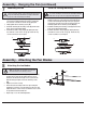
Assembly - Standard Ceiling Mount 1 2 Preparing for mounting □□ Remove the canopy ring (K) from the canopy (C) by turning □□ □□ Routing the wires □□ Route the wires exiting the top of the fan motor (D) into the decorative motor collar cover (F) and through the canopy ring (K). the ring to the right until it unlocks. Remove the mounting plate (A) from the canopy (C) by loosening the four screws on the top of the canopy (C). Remove the two non-slotted screws, and loosen the slotted screws.
Assembly - Close-To-Ceiling Mount 1 2 Close-to-Ceiling Mounting □□ Remove the canopy ring (K) from the canopy (C) by turning the □□ □□ □□ Routing the wires □□ Remove three of the six screws and lock washers (every other ring to the right until it unlocks. Remove the mounting bracket (A) from the canopy (C) by loosening the four screws on the top of the canopy (C). Remove the two non-slotted screws and loosen the slotted screws.
Assembly - Hanging the Fan (continued) 5 Hanging the fan WARNING: The hook as shown is only to balance the fan while attaching wiring. Failure to hang as shown may result in hook breaking, causing the fan to fall. The hook must pass from inside to the outside of the canopy. A A B □□ Carefully lift the fan motor assembly (D) up to the mounting bracket (A). C D □□ Seat the hanger ball portion of the ball/downrod assembly (B) in the mounting bracket socket.
Assembly - Hanging the Fan (continued) 7 Mounting the fan Close-to-Ceiling mounting WARNING: When using the standard ball/downrod mounting, the tab in the ring at the bottom of the mounting bracket must rest in the groove of the hanger ball. Failure to properly seat the tab in the groove could cause damage to the wiring. WARNING: The locking slots of the ceiling canopy are provided only as an aid to mounting.
Assembly - Attaching the Light Kit 9 10 Attaching the light kit CAUTION: To reduce the risk of electric shock, disconnect the electrical supply circuit to the fan before installing the light kit. CAUTION: Make sure the power is off before attaching or removing the glass shades. □□ Remove the three screws (QQ) from the black bracket below □□ □□ WARNING: Allow the glass shade to cool completely before removing. the fan motor assembly (D).
Operation Turn on the power and check the operation of the fan. The pull chain controls the fan speeds as follows: 1 pull - High, 2 pulls - Medium, 3 pulls - Low, 4 pulls - off The appropriate speed settings for warm or cool weather depends on factors such as the room size, ceiling height, and number of fans. The slide switch controls the direction of the blades: forward (switch left) or reverse (switch right) NOTE: Wait for the fan to stop before reversing the direction of blade rotation.
Care and Cleaning WARNING: Make sure the power is off before cleaning your fan. □□ Because of the fan’s natural movement, some connections may become loose. Check the support connections, brackets, and blade attachments twice a year. Make sure they are secure. It is not necessary to remove the fan from the ceiling. □□ Clean your fan periodically to help maintain its new appearance over the years.
Questions, problems, missing parts? Before returning to the store, call Hampton Bay Customer Service 8 a.m. - 6 p.m., EST, Monday-Friday 1-877-527-0313 HAMPTONBAY.COM Retain this manual for future use.
Artículo Núm. 795-838, 795-871, 795-904, 850-919, 850-193 Modelo Núm.: 51012, 51013, 51014, 51090, 51091 Modelo Núm. 52-CCT Aprobado por UL GUÍA DE USO Y MANTENIMIENTO VENTILADOR DE TECHO LYNDHURST DE 52 PLG (1,32 M) ¿Preguntas, problemas o piezas faltantes? Antes de regresar a la tienda, llama al Servicio al Cliente de Hampton Bay de Lunes a Viernes entre 8 a.m. y 6 p.m. (hora del Este de EE. UU.) 1-877-527-0313 HAMPTONBAY.
Tabla de Contenido Tabla de Contenido.............................................................. 2 Ensamblaje............................................................................ 7 Información de Seguridad................................................... 2 Funcionamiento.................................................................. 12 Garantía................................................................................. 3 Mantenimiento y Limpieza......................................
Garantía El proveedor garantiza de por vida, a partir de la fecha en que el comprador original lo adquiere, que el motor del ventilador no presenta defectos de fabricación ni de material al momento en que es enviado desde la fábrica.
Preinstalación (continuación) Herrajes incluidos NOTA: No se muestra el tamaño real de los herrajes.
Preinstalación (continuación) contenido del paquete A F B G C H D I E J Pieza Descripción Cantidad Pieza Descripción A Soporte deslizante para montaje (dentro de la cubierta) 1 B Ensamblaje de tubo bajante/bola C D Cantidad E Ensamblaje del soporte del kit de luces 1 F Cubierta decorativa del collarín del motor 1 1 G Aspa 5 Cubierta con aro incorporado 1 H Soporte de aspa 5 Ensamblaje del motor del ventilador 1 I Pantalla de vidrio 4 J Bombilla CFL, máximo de 14 Wa
Instalación Opciones de Montaje ADVERTENCIA: Para reducir el riesgo de incendio, descarga eléctrica o lesiones personales, monta el ventilador sobre una caja eléctrica marcada como “aprobada como soporte de ventiladores de 35 lb (15,9kg) o menos”, y usa los tornillos de montaje que vienen con la misma. Las cajas eléctricas utilizadas comúnmente para el soporte de lámparas podrían no servir como soporte de ventilador y, tal vez, deban ser reemplazadas. En caso de duda, consulta a un electricista calificado.
Ensamblaje - Montaje Estándar en Techo 1 2 Preparación para el montaje □□ Retira el aro (K) de la cubierta (C), girándolo hacia la derecha □□ □□ Disposición de los cables □□ Inserta los cables que salen por la parte superior del motor del ventilador (D) en la cubierta decorativa del collarín del motor (F) y a través del aro de la cubierta (K). hasta soltarlo. Retira la placa de montaje (A) de la cubierta (C) aflojando los cuatro tornillos en la parte superior de la cubierta (C).
Ensamblaje - Montaje Cerca del Techo 1 2 Montaje Cerca del Techo □□ Retira el aro (K) de la cubierta (C), girándolo hacia la derecha □□ □□ □□ Disposición de los cables □□ Retira tres de los seis tornillos y arandelas de seguridad hasta soltarlo. Retira el soporte de montaje (A) de la cubierta (C) aflojando los cuatro tornillos en la parte superior de la cubierta (C). Quita los dos tornillos sin ranura y afloja los tornillos ranurados.
Ensamblaje — Cómo Colgar el Ventilador (continuación) 5 Cómo colgar el ventilador ADVERTENCIA: El gancho usado como se muestra es sólo para sostener el ventilador mientras se conectan los cables. Si no se cuelga como se muestra puede romperse el gancho, y el ventilador se caerá. El gancho debe pasar de adentro hacia fuera de la cubierta. A A B □□ Con cuidado alza el ensamblaje del motor del ventilador (D) C D hasta el soporte de montaje (A).
Ensamblaje — Cómo Colgar el Ventilador (continuación) 7 Cómo montar el ventilador Montaje Cerca del Techo ADVERTENCIA: Cuando uses el ensamblaje del tubo bajante/ bola estándar, la pestaña en el aro en la parte inferior del soporte de montaje debe encajar en la ranura de la bola de soporte. Si la pestaña no se asienta correctamente en la ranura, se puede dañar el cableado. ADVERTENCIA: Las ranuras de encaje de la cubierta del techo solo sirven de ayuda durante el montaje.
Ensamblaje - Cómo Instalar el Kit de Luces 9 10 Cómo instalar el kit de luces PRECAUCIÓN: Para disminuir el riesgo de descarga eléctrica, desconecta el circuito de energía del ventilador antes de instalar el kit de luces. PRECAUCIÓN: Asegúrate de que la corriente esté cortada antes de montar o retirar las pantallas de vidrio. □□ Quita los tres tornillos (QQ) del soporte negro debajo del □□ □□ ADVERTENCIA: Espera que la pantalla de vidrio se enfríe completamente antes de retirarla.
Funcionamiento Conecta la electricidad y verifica el funcionamiento del ventilador. La cadena para halar controla las velocidades del ventilador de la siguiente manera: 1 vez: Alto, 2 veces: Medio, 3 veces: Bajo, 4 veces: Apagado Las configuraciones de velocidad apropiadas para clima cálido o frío dependen de factores como el tamaño de la habitación, la altura del techo y la cantidad de ventiladores.
Mantenimiento y Limpieza ADVERTENCIA: Asegúrate de que la corriente esté cortada antes de limpiar el ventilador. □□ Debido al movimiento natural del ventilador, algunas conexiones pueden aflojarse. Revisa las conexiones de soporte, los soportes y los accesorios de las aspas dos veces al año. Verifica que estén seguros. No es necesario desmontar el ventilador del techo. □□ Limpia el ventilador con frecuencia para que luzca como nuevo con el pasar de los años.
¿Preguntas, problemas o piezas faltantes? Antes de regresar a la tienda, llama al Servicio al Cliente de Hampton Bay de Lunes a Viernes entre 8 a.m. y 6 p.m. (hora Estándar del Este de EE. UU.) 1-877-527-0313 HAMPTONBAY.COM Conserva este manual para usarlo en el futuro.