Refrigeration Systems Installation Manual 07/14 Rev.
Table of Contents Tools Required General Information Unpacking & Inspection for Ceiling Mount Unpacking & Inspection for Remote Wall Mount Refrigeration Systems Installation Instructions Freezer Models 100 & 150 or Cooler Model 075 General Installation Instructions for Ceiling Mount Remote Refrigeration Systems With Electric Vaporizer With Optional Electric Condensate Vaporizer Instructions for Pre-Charged Lines Instructions for Wire Harness Outdoor Systems Membrane Roofing Material Operation Standard Te
Tools Required Tools required for uncrating and installation of the • • • • • • • 3 Refrigeration System Safety Glasses Metal Snips Pry Bar Hammer Adjustable Open End Wrench (2) Drill Driver Pencil 07/14 Rev.
Refrigeration Systems-General Information Ceiling mounted Refrigeration System General Information This Refrigeration System was produced utilizing the latest in manufacturing technology, the highest quality materials available, along with innovations that make it a distinctive product in its field. Despite rigid controls in the production of the product, there is no substitute for thoroughly reading and UNDERSTANDING the instructions that follow. The result will be an orderly and efficient installation.
Refrigeration Systems-General Information Unpacking & Inspection--Remote Refrigeration Systems Check the Delivery Receipt for the number of pieces that made up the shipment and make sure that the number of pallets, boxes or crates agrees with that number. Each piece should be clearly marked with the same five-digit order number that appears on the Delivery Receipt as the shipper's number.
General Installation Instructions WALL MOUNTED REFRIGERATION SYSTEMS Installation Instructions Note: If the system to be wall mounted is a freezer model 100 or 150 or cooler model 075, please see the next section with special instructions on mounting these units. Carefully raise the entire refrigeration system and insert the projecting sleeve of the evaporator section into the opening of the walk-in wall.
General Installation Instructions Freezer Models 100 and 150 or Cooler Model 075 1. After uncrating, before attempting to attach the refrigeration system to the walk-in, a substantial temporary support should be built. The support should be approximately 28 inches high and placed directly below the wall opening of the walk-in. Note: Due to the weight of these systems it is highly recommended that proper lifting equipment, such as a fork truck, be utilized during installation. 2.
General Installation Instructions General Installation Instructions This section has the general instructions for installing the ceiling mounted Refrigeration System. Before proceeding, also see the following section on mounting "Remote Systems with Electric Vaporizer", if applicable. Note: Proper "temporary" interior support must be added during the installation of the refrigeration.
General Installation Instructions Note: The process above is the same when locating/installing the insulated evaporator section of a Remote Refrigeration System. After the system is in place, make sure that the bolts fastening the condensing unit section to the evaporator section are loose enough so that the two sections can adjust to the ceiling surfaces. Note: On large systems, 100 series and above, the units are placed on a rack assembly and do not have these bolts connecting the two sections together.
Remote Refrigeration Systems Remote Systems with Electric Vaporizer Set the Refrigeration System evaporator section over the hole in the ceiling section. Align the tabs on the side of the insulated evaporator section with the predrilled holes in the ceiling section. Before proceeding to the next step, the evaporator cover should be removed. Look inside the evaporator section and be sure the air divider in the ceiling section lines up with the black gasket divider in the evaporator section.
Remote Refrigeration Systems Optional Feature - Electric Condensate Vaporizer Note the location of the condensate drain line coming from the evaporator. Locate the electric vaporizer so the condensate will run into it. If the vaporizer cannot be located at the drain line, use the supplied plastic tubing, copper elbow, and hose clamp(s) as required to extend the drain line. Cut the plastic tubing to length as required. Provide power to the electric vaporizer per local and national electric codes.
Remote Refrigeration Systems INSTRUCTIONS FOR PRE-CHARGED LINES - REMOTE SYSTEMS By employing self-sealing refrigeration couplings, the condensing unit section, evaporator section, and the connecting tubing are separately pre-charged with refrigerant and leak tested at the factory before shipment. Follow steps 1-8 below to install the connecting tubing at both the condensing unit and the evaporator section. 1. Carefully uncoil the suction line.
Remote Refrigeration Systems 8. Once the suction line is connected, the sponge insulation must be pulled up to cover the quick connects. Tie or tape off the insulation to prevent air infiltration and reduce water/ice formation on the suction line. All valves are open and the system is ready for operation. Remember, the refrigeration couplings on this system are self sealing and, if the need ever arises, the couplings may be disconnected without any loss of refrigerant.
Remote Refrigeration Systems with Wire Harness 1. All systems with a wire harness will have a “K” at or near the end of the model number. Example: RCPB100DC-A-50K. 2. These systems will come with the wire harness already wired to the condensing unit section of the refrigeration system. 3. These wire harnesses will have approved seal tight conduit and connectors. 4. Before power is connected to the condensing unit section it should first be wired to the evaporator section with the wire harness provided.
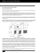
Outdoor Systems Outdoor Systems Utilizing a Membrane Roofing Material Curb 1. After the walk-in is completely assembled, place the curb face down on top of the ceiling sections (curb is fastened to crate base during shipping and must be removed and installed prior to membrance roof installation). To ensure proper opening alignment, mark the outside portion of the curb on the ceiling sections with a marking pencil. 2.
Outdoor Systems 4. Set the Refrigeration System over the opening in the curb. Remove the enclosure from the condensing unit portion of the system and drill two 9/16” holes through the condensing unit base plate, membrane roof material and the foamed ceiling section. The holes should be located on opposite sides of the unit. Insert one 1/2” threaded nylon rod into each hole.
Operation OPERATION STANDARD TEMPERATURE (COOLER) SYSTEMS The automatic air defrost Capsule Pak™ Refrigeration System for coolers is a basic, unitized refrigeration system. The system is designed to provide normal storage temperatures in a Kold Locker™ Walk-in with a minimum of effort during initial installation. The system consists of a complete condensing unit, an evaporator coil, a method for controlling the temperature, and a time switch for setting "off cycle" defrost.
Operation LOW TEMPERATURE (FREEZER) SYSTEMS The low temperature, automatic electric defrost Capsule Pak™ Refrigeration System is the most dependable and readily understood equipment available. It employs a basic refrigeration system with electric elements to provide heat for defrosting. Important: It is the installing contractor’s responsibility to check the operation upon start-up and make necessary temperature control or thermal expansion valve adjustments as required for proper operation.
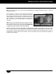
Operation Time Clock Adjustments: Setting the correct time of day: Simply rotate the minute hand clockwise until the correct time of day on the outer dial is aligned with the triangle marker on the inner dial. In referring to the illustration, the correct time of day shown is 8:00 a.m. Number of defrosts per day: The time switch is factory set to provide four defrosts per day. If more defrosts are required, move additional white tabs at the desired time.
Operation/Maintenance Drain Tube Heater Low temperature ceiling mounted Capsule Pak™ Refrigeration Systems may employ a low wattage, electric heater strip. This heater is spirally wound around the condensate drain tube that extends from the drain pan below the evaporator coil to the evaporator section housing wall. This heater is energized continually to provide positive discharge of the condensate moisture to the hot gas vaporizer. The heater and drain tube are covered with an insulated tape.
Maintenance Evaporator Drain Pan Removal - Ceiling Mounted Models Note: Model numbers ending with the letter "A" Remove the drain pan retainer that is located near the end of the drain pan opposite the drain tube. It is secured by a thumbscrew. Release the drain tube stub from the drain discharge tube and remove the pan. On freezer models, a drain pan heater is secured to the drain pan bottom by short brackets. Only a slight effort is required to release the heater element from the brackets.
Maintenance Analysis MALFUNCTION POSSIBLE CAUSE SOLUTION Compressor will not start no hum 1. 2. 3. 4. 5. Unplugged or power off Fuse blown or removed Overload tripped Control stuck open Wiring incorrect 1. 2. 3. 4. 5. Plug in service cord or turn power on Replace fuse Determine reasons and correct Repair or replace Check wiring against the diagram Compressor will not start hums but trips on overload protector 1. 2. 3. 4.
Manual de instalación del Sistema de refrigeración 07/14 Rev.
Tabla de contenidos Herramientas necesarias Información General Desembalaje e inspección para montaje en el techo Desembalaje e inspección remotos Sistema de refrigeración de montaje en pared Instrucciones de instalación Modelos de congelador 100 y 150 o modelo de enfriador 075 Instrucciones generales de instalación para montaje en el techo Sistemas de refrigeración remotos Con vaporizador eléctrico Con vaporizador condensado eléctrico opcional Instrucciones para líneas precargadas Instrucciones del arnés
Herramientas Herramientas requeridas para el desempaque e instalación del sistema de refrigeración • • • • • • • 3 requeridas Gafas de seguridad Cizallas para metal Barra de palanca Martillo (2) Llave ajustable para Taladro Lápiz tuercas 07/14 Rev.
Sistemas de refrigeración - Información general Sistema de refrigeración Información General Este sistema de refrigeración fue producido utilizando tecnología de punta en su fabricación, los materiales de más alta calidad disponibles, junto con innovaciones que lo hacen diferente en su campo. A pesar de los estrictos controles en la producción, no hay sustituto para la lectura y COMPRENSIÓN total de las instrucciones que siguen. El resultado será una instalación eficiente y ordenada.
Sistemas de refrigeración - Información general Desempaque e inspección--Sistemas remotos de refrigeración Compruebe en el recibo de entrega el número de piezas que componen el envío y asegúrese que el número de bandejas de carga, cajones o cajas estén de acuerdo con estas anotaciones. Cada pieza debe ser marcada claramente con el mismo número de orden de cinco dígitos que aparece en el recibo de entrega como así también el número del expedidor.
Instrucciones generales de instalación Sistemas De Refrigeracion Para Montar En Pared INSTRUCCIONES DE INSTALACIÓN NOTA: Si el sistema que debe montarse a la pared es un modelo de congelador 100 o 150 o un modelo de enfriador 075, consulte la sección siguiente con instrucciones especiales para montar estas unidades. Eleve con cuidado todo el sistema de refrigeración e inserte la manga protectora de la sección del evaporador en la apertura de la pared de acceso.
Instrucciones generales de instalación Modelos de congelador 100 y 150 o modelo de enfriador 075 1. Después de desembalar, luego de intentar conectar el sistema de refrigeración al acceso, debe construirse un soporte sustancial temporal. El soporte debe colocarse a aproximadamente 28 pulgadas (71 cm.) de alto y directamente por debajo de la apertura del acceso en la pared.
Instrucciones generales de instalación Instrucciones generales de instalación Esta sección contiene las instrucciones generales para montar sobre el techo el Sistema de refrigeración. Antes de proceder, vea también la siguiente sección sobre montaje "Sistemas remotos con vaporizador eléctrico", si fuera necesario aplicarlos. Nota: El término "temporal" interior se debe agregar la compatibilidad durante la instalación de refrigeración.
Instrucciones generales de instalación de acceso total. Este método no es práctico y no debería ser usado con sistemas más grandes que las series 100 o superiores, como por ejemplo un modelo CPF 100, CPF150 o CPF151. Nota: El proceso mencionado arriba es el mismo al colocar/ instalar la sección evaporadora aislada de un sistema de refrigeración Remote.
Sistema de refrigeración Remote Sistemas remotos con vaporizador eléctrico Coloque la sección evaporadora del sobre la apertura del secciones de techo. Alinee las lengüetas sobre los costados de la sección del evaporador aislado con los agujeros que ya están perforados en la sección de techo. Antes de proceder al siguiente paso, debe quitar la cubierta del evaporador.
Sistema de refrigeración Remote Características opcionales - Vaporizador condensador eléctrico Advierta la ubicación de la línea de drenaje de la condensación que viene desde el evaporador. Ubique el vaporizador eléctrico de modo que la condensación caiga en él. Si el vaporizador no puede ser ubicado en la línea de drenaje, use la tubería plástica provista con codos de bronce y las abrazaderas de mangueras que sean necesarias para prolongar la línea de drenaje.
Sistema de refrigeración Remote INSTRUCCIONES PARA SISTEMAS REMOTOS DE LÍNEAS PRE-CARGADAS Empleando uniones auto-selladoras, la sección de la unidad condensadora, la sección evaporadora y la cañería de conexión, están pre cargadas por separado con refrigerante y comprobado en fábrica antes de su envío para asegurarse que no hayan filtraciones. Siga los pasos de 1a 8 de más abajo, para instalar la cañería de conexión tanto en la unidad condensadora como en la sección de evaporación. 1.
Sistema de refrigeración Remote 8. Una vez que la línea de succión esté conectada, la esponja aisladora debe ser jalada hacia arriba para cubrir los empalmes rápidos. Ate o pegue con cinta adhesiva la aislación para evitar filtraciones y reducir la formación de agua/hielo en la línea de succión. Todas las válvulas están abiertas y el sistema está listo para el funcionamiento.
Sistemas de refrigeración Remotos con Arnes Para Cables 1. Todos los sistemas con arnés para cables tienen una “K” en o cerca del final del número del modelo. Ejemplo: RCPB100DC-A-50K. 2. Estos sistemas vienen con un arnés para cables ya cableado en la sección de la unidad de condensación del sistema de refrigeración. 3. Estos arnés para cables tienen un conducto con sello de ajuste y conectores aprobados. 4.
Sistemas de exteriores Sistemas de exteriores que utilizan material de membrana de techo 1. Una vez que el acceso está completamente armado, coloque la barbada hacia abajo en la parte superior de las secciones del techo (la barbada se ajusta a la base del cajón durante el envío y debe retirarse e instalarse antes de la instalación de la membrana para el techo). Para asegurarse una alineación correcta, marque con un lápiz marcador la parte externa del cuadro portador sobre las secciones de techo. 2.
Sistemas de exteriores Capsule Pak™ 4. Ubique el sistema de con cubeirta refrigeración sobre la abertura en el cuadro portador. Retire el Membrana gabinete de la parte de la unidad de techo de condensación del sistema y taladre dos orificios de 9/16” (12 mm.) a través de la placa de base de la unidad de condensación, del material de la membrana del techo y de la sección del techo revestida. Los agujeros deben estar en los costados Abertura opuestos de la unidad.
Operación OPERACIÓN SISTEMAS DE TEMPERATURA ESTÁNDAR (ENFRIAMIENTO) El Sistema de refrigeración Capsule Pak™ descongelador de aire automático para enfriadores es un sistema de refrigeración básico y unificado. El sistema está diseñado para ofrecer temperaturas de almacenamiento normales en una cámara de enfriado Kold Locker™ con un mínimo esfuerzo durante la instalación inicial.
Operación SISTEMAS DE BAJA TEMPERATURA (CONGELADOR) Las bajas temperaturas, la descongelación eléctrica automática de los sistemas de refrigeración son los equipos disponibles más confiables y fáciles de entender. Emplea un sistema básico de refrigeración con elementos eléctricos para proveer calor para descongelar.
Operación Terminación del ciclo de descongelación A medida que progresa el ciclo de descongelación y la acumulación de escarcha se funde desde las aletas del serpentín evaporador, la temperatura de las superficies aletadas del serpentín evaporador se elevará proporcionalmente a la remoción de la escarcha.
Operación/Mantenimiento Esta unidad se usa para controlar los ajustes de temperatura y de descongelación. Consulte las instrucciones separadas que se incluyen para el funcionamiento de este control. Tubo de drenaje del calentador Todos los sistemas de refrigeración de bajas temperaturas montados en el techo, emplean calentadores de banda de baja potencia en vatios.
Mantenimiento Mantenimiento Remoción de la bandeja de drenaje del evaporador - Extracción de la bandeja de drenaje del evaporador: modelos para montaje en el techo Nota: Números de modelo que terminan con la letra "A" Retire el retén de la bandeja de drenaje que está ubicado cerca del extremo de la bandeja de drenaje opuesto al tubo de drenaje. Está asegurado con un tornillo de apriete manual. Libere el cabo del tubo de drenaje del tubo de descarga de drenaje y retire la bandeja.
Análisis de mantenimiento PROBLEMAS DE FUNCIONAMIENTO CAUSAS POSIBLES SOLUCIÓN El compresor no arranca no produce zumbido 1. 2. 3. 4. 5. Desenchufado o no recibe corriente eléctrica Fusible quemado o falta del mismo Se interrumpe por sobrecarga El control se atasca abierto Cableado incorrecto 1. 2. 3. 4. 5.