Spray Height Control System UC4+ Severe Terrain Option Low Profile Brackets – John Deere Installation Manual Improving the competitiveness of Industry and Agriculture through Precision Measurement
Printed in Canada Copyright 2010 by NORAC Systems International Inc. Reorder P/N: 4465BC+JD+INST Rev A (UC4+ Severe Terrain Option Low Profile Brackets – John Deere) NOTICE NORAC Systems International Inc. reserves the right to improve products and their specifications without notice and without the requirement to update products sold previously. Every effort has been made to ensure the accuracy of the information contained in this manual.
TABLE OF CONTENTS 1 INTRODUCTION .................................................................................................................................................. 1 2 GENERAL SYSTEM DESCRIPTION ................................................................................................................... 2 3 PARTS LISTS..........................................................................................................................................................
1 INTRODUCTION This kit provides the necessary parts that will add the severe terrain option to your sprayer. These parts integrate into your existing NORAC UC4+ Sprayer Height Control System for minimal setup of this feature. Please take the time to read this manual completely before attempting to install the system. A thorough understanding of this manual will ensure that you receive the maximum benefit from the system.
2 GENERAL SYSTEM DESCRIPTION Figure 1 depicts the general system layout of the UC4+ Spray Height Control system. Figure 1: System Components and General Location NOTICE: Every effort has been made to ensure the accuracy of the information contained in this manual. All parts supplied are selected specially to fit the sprayer to facilitate a complete installation. However, NORAC cannot guarantee all parts fit as intended due to the variations of the sprayer by the manufacturer.
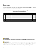
3 PARTS LISTS The parts that come with your UC4+ Spray Height Control System are listed in Table 1. The item number on the left side of this table references each part. Please ensure that all parts in your kit are present before proceeding with your installation. Table 1: Severe Terrain Option Parts Item Part Number Name Quantity B05 44706-01 KIT CABLE TIE BLACK 10 PCS 21 IN 150 PCS 7.
The parts that come with your Severe Terrain Option kit are shown below in their general installation configuration.
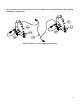
4 INSTALLATION PROCEDURE 4.1 SENSOR INSTALLATION 1. Mount the Low Profile Sensor Mounting Brackets (B20) onto the boom as show in Figure 3 and Figure 4 with the mounting base in front of the tube. 2. Mount the sensor brackets onto the boom half way between the tip and center of the sprayer (Figure 8). If possible, mount the sensor brackets while the booms are in their folded position to ensure that they will not interfere with anything when the boom is folded for transport. 3.
General Mounting Ultrasonic Sensors: Rules for UC4+ a) In its lowest position, the sensor must be 9 inches (23 cm) or more from the ground. Front Figure 5: Low Profile Bracket Mounted with Exhaust Clamps b) Ensure that there are no obstructions within a 12-inch diameter circle projected directly below the center of the sensor. c) The sensor should be approximately vertical at normal operating heights.
Figure 8: Sensor Serial Number Installation Location * Existing Parts * New Parts 7
4.2 ELECTRICAL INSTALLATION 1. Disconnect the existing cable C02B from the existing cable C02. 2. Connect cable C02B included in this kit between the cables as shown in Figure 9. 3. Route the free ends of cable C02B to the new sensors and connect to the sensor connectors. 4. Cable tie all cables to existing hoses or cables. It is recommended to follow existing cables or hoses when routing the cables.
4.3 COMPLETING THE INSTALLATION 1. Start up your sprayer and test the sprayer’s functionality. The NORAC Control Panel does not need to be powered up for the original switches to function. Unfold the booms and raise/lower each boom and main section. Again confirm that the cabling/hoses are agreeable to the entire range of motion. 2. If any functions do not work, review the hydraulic and electrical portions of this manual to check for proper installation.
5 ELECTRICAL REFERENCE – CABLE DRAWINGS 5.
www.norac.ca Canada NORAC Systems International Inc. CALL TOLL FREE: 1-800-667-3921 (306)664-6711 SHIPPING ADDRESS: 3702 Kinnear Place Saskatoon, SK S7P 0A6 United States NORAC, Inc.