GS2-PT02 John Deere GS2 2600, 1800 and GS3 2630 All European Trailed Display Kit Installation Manual
Printed in Canada Copyright 2010 by NORAC Systems International Inc. Reorder P/N: 54VT-GS2-PT02-INST Rev E (John Deere GS2 2600, 1800 and GS3 2630 All European Trailed Display Kit) NOTICE: NORAC Systems International Inc. reserves the right to improve products and their specifications without notice and without the requirement to update products sold previously. Every effort has been made to ensure the accuracy of the information contained in this manual.
Contents 1 INTRODUCTION ...................................................................................................... 2 1.1 List of Parts ..........................................................................................................................................................................2 2 TECHNICAL SPECIFICATIONS ............................................................................. 3 3 INSTALLATION ..................................................................
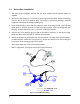
1 Introduction The John Deere GS2 2600, 1800 and GS3 2630 – All Trailed Sprayer Display Kit Manual is intended to be used in conjunction with the UC5 Spray Height Control Installation Manual. This manual provides instructions to interface the UC5 Control Module to the John Deere GS2 2600, 1800 and GS3 2630 Displays. For installation of the rest of the UC5 Spray Height Control System please refer to the sprayer specific manual provided with the kit. 1.
2 Technical Specifications CAN ICES-3(A)/NMB-3(A) This device complies with part 15 of the FCC Rules. Operation is subject to the following two conditions: (1) This device may not cause harmful interference, and (2) this device must accept any interference received, including interference that may cause undesired operation. This equipment has been tested and found to comply with the limits for a Class A digital device, pursuant to part 15 of the FCC Rules.
3 Installation The following instructions are for installation on a trailed sprayer. On a trailed sprayer if the CANbus and power supply are located on the sprayer, the control module may also be installed on the sprayer (Section 3.2). 3.1 Control Module on Tractor 1. Securely mount the control module (E01) inside the tractor cab. 2. Tee the CANbus interface cable (C40) in to the John Deere CANbus.
3.2 Control Module on Sprayer 1. Securely mount the control module (E01) on the sprayer near the CANbus connection. 2. Tee the CANbus interface cable (C40) in to the John Deere CANbus. Connect the 6 pin Deutsch plug on cable C40 to the 2-way coupler (E12). 3. Connect cable C41 between the 2-way coupler (E12) and the end of the control module with only one Deutsch connector. 4. Connect cable C30 to the CANbus connector. Connect the other end of C30 to an appropriate power supply.
3.3 Switch Box Installation 1. This step of the installation assumes that the input module and all required cables are installed. 2. Disconnect cable C20 (Thru 2 connector) from the Input Module (E03). Remove the wedge from the face of the 12 pin Deutsch plug. The wedge is removed by inserting a small flat implement underneath the wedge and lifting it up. 3. Insert the Roll CW pin from C26 into position 3 of the 12 pin plug on C20.
4 Cable Drawings 4.
4.
4.3 4.
4.
Appendix A: Alternate Configuration If your sprayer has European style slant control, you will need to reconfigure the switch box as shown below. This is only required for sprayer types which are driving the slant output from the Input Module.
Canada NORAC Systems International Inc. Phone: (+1) 306 664 6711 Toll Free: 1 800 667 3921 Shipping Address: 3702 Kinnear Place Saskatoon, SK S7P 0A6 United States NORAC, Inc. Phone: (+1) 952 224 4142 Toll Free: 1 866 306 6722 Shipping Address: 6667 West Old Shakopee Road, Suite 111 Bloomington, MN 55438 Europe NORAC Europe Phone: (+33) (0)4 26 47 04 42 Shipping Address: Rue de l’hermitage 01090 GUEREINS France www.norac.