JD10A John Deere (4930, 4940) Active RollTM with Proportional Main Lift Installation Manual
Printed in Canada Copyright 2009 by NORAC Systems International Inc. Reorder P/N: UC5-BC-JD10A-INST Rev C (John Deere 4930 and 4940 Active Roll with Proportional Main Lift) NOTICE: NORAC Systems International Inc. reserves the right to improve products and their specifications without notice and without the requirement to update products sold previously. Every effort has been made to ensure the accuracy of the information contained in this manual.
Contents 1 Introduction ................................................................................................................ 1 2 Technical Specifications ............................................................................................ 2 3 General UC5 System Layout .................................................................................... 3 4 Kit Parts .....................................................................................................................
1 Introduction Congratulations on your purchase of the NORAC UC5 Spray Height Control System. This system is manufactured with top quality components and is engineered using the latest technology to provide operating reliability unmatched for years to come. When properly used the system can provide protection from sprayer boom damage, improve sprayer efficiency, and ensure chemicals are applied correctly. Please take the time to read this manual completely before attempting to install the system.
2 Technical Specifications CAN ICES-3(A)/NMB-3(A) This device complies with part 15 of the FCC Rules. Operation is subject to the following two conditions: (1) This device may not cause harmful interference, and (2) this device must accept any interference received, including interference that may cause undesired operation. This equipment has been tested and found to comply with the limits for a Class A digital device, pursuant to part 15 of the FCC Rules.
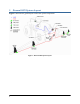
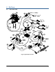
3 General UC5 System Layout Figure 1 illustrates the general layout of the UC5 system components: Figure 1: General UC5 System Layout 3
4 4.
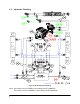
4.2 Hydraulic Plumbing Figure 3: JD10A Hydraulic Plumbing Note: Part numbers shown in RED are from fittings kit H11 (44865-37). Part numbers shown in GREEN are from fittings kit H12 (44865-66).
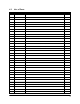
4.3 List of Parts Item Part Number Name Quantity B05 44706-01 KIT CABLE TIE BLACK 10 PCS 21 IN 150 PCS 7.
4.
4.
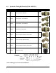
4.6 Item Hydraulic Fitting Kit Details (P/N: 44865-66) Part Number Name F10 44927 ORIFICE INSERT .031 IN ONE WAY 1 F11 44975 ORIFICE INSERT .
5 Pre-Install Checklist The pre-install checklist is necessary to check the existing sprayer functionality before the installation. 1. Unfold the sprayer over a flat, unobstructed area (i.e. no power lines…etc.). 2. Ensure all boom-fold operations are functional (place a check mark in boxes below). 3. Bring engine to field-operational RPM and record below. 4. Record the time (seconds) it takes for a full stroke for all boom functions. To ensure repeatable measurements, take the average of 3 trials. 5.
6 6.1 Ultrasonic Sensor Installation Ultrasonic Sensor Serial Number Arrangement When installing the UC5 sensors, start with the smallest serial number on the left-hand side, and proceed to the largest serial number on the right hand side. Each UC5 sensor has a serial number stamped on the sensor housing. Apply a light coating of the supplied Permatex Anti-seize grease to all threaded parts upon installation.
6.2 Ultrasonic Wing Sensor Mounting Guidelines The following guidelines will ensure optimal sensor performance and prevent sensor measurement error. 1. In its lowest position, the sensor must be 9 inches (23 cm) or more from the ground. 2. Ensure that there are no obstructions within a 12-inch diameter circle projected directly below the center of the sensor. 3. The sensor should be approximately vertical at normal operating heights.
6.3 Low Profile Bracket Mounting Guidelines 1. Minimize the distance between the bolts to prevent bending the bracket and prevent the bracket from loosening over time. 2. Ensure the bracket is mounted tight against the bottom of the boom, minimizing the distance between the boom structure and the angled flange. Figure 7: Bracket Mounting Guidelines A problem can arise if a sensor is not mounted correctly. It is possible for the sensor to read off of the boom instead of the ground.
6.4 Wing Sensor Installation 1. The sensor bracket should be oriented forward (ahead of the boom). 2. Typically the best mounting location for the wing sensor brackets will be near the end of the boom tips, approximately two feet (60cm) from the end. 3. Depending on the boom design, some breakaway sections will lift upwards as they break back. If the sensor is mounted to this portion of the boom, the system will force the boom downwards towards the ground as the boom folds backwards. 4.
6.5 Rainflap Installation Rainflaps are only installed in the wing sensor brackets. 1. Insert one side of the rainflap rod into the pre-bent hinge tab on the sensor bracket. (Figure 10) Figure 10: Rainflap Rod in Pre-Bent Hinge Tab 2. Align the other side of the rainflap rod with the unbent hinge tab. (Figure 11) Figure 11: Align Rainflap Rod 3. Bend the hinge tab inward over the rainflap rod until the hinge tab fits securely in the detent groove on the backside of the sensor bracket.
6.6 Ultrasonic Main Lift Sensor Mounting Guidelines The following guidelines will ensure optimal sensor performance and prevent sensor measurement error. 1. In its lowest position, the sensor must be 9 inches (23 cm) or more from the ground (A). 2. The centerline of the acoustic cone should be approximately vertical at normal operating heights (A). 3. The bottom of the sensor must be at least 9 inches in front of the spray nozzles and boom structure (B). (This does not apply for the main lift sensor) 4.
6.7 Main Lift Sensor Installation Figure 13: Main Lift Bracket Assembly 1. There are a variety of ways to mount the main lift bracket on most sprayers. The bracket should position the sensor approximately in the center of the sprayer, forward of the boom. An example of this mounting is illustrated in Figure 14. 2. Mount the ultrasonic sensor to the main lift bracket. Run the sensor cable down the center of the main lift bracket tube.
7 Module Installation An optional module mounting bracket kit is available for purchase from NORAC. The mounting brackets are compatible with control modules and input modules. One kit is needed per module. Item Part Number Name B20 43708 UC5 MOUNTING BRACKET KIT (CONTROL AND INPUT MODULES) 7.1 Quantity 1 Control Module 1. Refer to Figure 1 and Figure 15. 2. Securely mount the control module (E01) inside the sprayer cab using screws, cable ties or optional brackets. 3.
7.2 Valve Module 1. Install the valve module (E02) to the top of the NORAC valve block. Orient the 6-pin Deutsch (CANbus) connectors towards the “P” and “T” ports with the label facing up. Output Number 1 2 3 4 5 6 7 8 Normal Function Left Up Left Down Right Up Right Down Main Up Main Down Roll CW Roll CCW Figure 16: Valve Module 2. Verify the valve coil connectors are oriented vertically (Figure 17). Figure 17: Align Coils 3. Place the valve module between the valve coils.
Figure 18: Valve Module Bracket Installation 5. Connect the valve module CANbus to cable C01 from the control module. Route cable C02 from the other CANbus connector to the input module. 6. With the valve module securely mounted to the valve block, connect the valve cables (C10), to the valve coils. 7. Connect the temperature probe to the valve block using the supplied 3/8” x 1/2” hex bolt.
7.3 Input Module 1. Install the input module (E03) on the boom near the John Deere valve block. Secure it to the boom using cable ties or optional brackets. 2. Connect the CANbus cable (C02) from the valve module to the input module. 3. Insert the 12 pin plug (P02) into the OEM 3 connector on the end of the input module Figure 20: Input Module Connections 4. Connect the 12 pin connector on the tilt interface cable (C20) to the Thru 2 connector on the side of the input module.
Figure 21: John Deere Valve Block with Electrical Connectors 6. Route the long cable (with Deutsch connectors) on C21 under the sprayer. Connect the tee connectors into the jam valve connector, located at the JD shuttle valve, under the sprayer (Figure 22).
8 Connecting the Sensors to the CANbus 1. Route cable C03 from the input module to the 8-way coupler (E11). Fasten the 8-way coupler to the boom with cable ties. 2. Connect the main lift sensor to the 8-way coupler using cable C02 and a 2-way coupler (E12). Cable C02 and item E12 may not be needed if the 8-way coupler is mounted close enough to the main lift sensor. 3. Connect the active roll sensor to the 8-way coupler using cable C03 and a 2-way coupler (E12). 4.
9 Hydraulic Installation Ensure all pressure has been bled from the system before disconnecting any lines or fittings. Hydraulic pressure will exist on the wing tilt circuits unless the wings are being supported by other means. You may wish to perform the hydraulic installation with the wings in transport position, resting on the ground or with the tilt cylinders fully extended. Component failure due to oil contamination is not covered under the NORAC UC5 system warranty.
9.2 Valve Assembly 1. On a clean surface remove the plastic plugs from the block. 2. Install the 6MB-6MOR (F02) fittings into the “P” and “T” ports. Tighten to 18 ft-lbs (24 Nm). 3. Install the 6MB-6MOR (F02) fittings into the “A” and “B” ports of the two stations closest to the “P” and “T” ports. Tighten to 18 ft-lbs (24 Nm). 4. Install the orifice (F08) and the 6MB 6MOR fitting (F05) into the “B” port of the 3rd station (furthest from the “P” and “T” ports) of the block. 5.
9.3 Valve Block Mounting 1. A good mounting location for the valve block on the John Deere is illustrated in Figure 26. 2. Insert the threaded rod into the block and use a hex nut to hold the rod. The block holes are 3/8” NC-1” deep. If bolts are used instead of the threaded rod, ensure the bolts thread in at least 3/8”. 3. Use the remaining hardware to secure the block to the sprayer. 4. Cut off excess threaded rod, if necessary.
9.4 Removing the Rubber Bumpers, Springs and Dampers The springs are under compression and must be retained during disassembly. Failure to ensure the spring forces are removed safely may result in injury or damage to the equipment. 1. Remove the rubber bumpers (Figure 27) from each side of the sprayer boom. Figure 27: Rubber Bumpers 2. The springs to be removed are located on the bottom rear of the sprayer boom (Figure 28).
When all the boom suspension components (springs, dampers and bumpers) are removed, the boom may roll to one side or move unexpectedly. 3. Remove the upper and lower mounting bolts and remove the damper from each side of the sprayer boom (Figure 29).
9.5 Active Roll Mounting Bracket Installation 1. Install the mounting bracket as shown in Figure 30. Ensure the stop on the lower mount is outside the frame. 2. Tighten the mounting bolts 50-70 ft-lbs.
9.6 Linear Roll Cylinder Assembly and Installation The linear roll cylinder must be mounted on the right hand side of sprayer. 1. In the linear roll cylinder crate is the linear roll cylinder, boom target, spring target and sensor bracket. Figure 33: Linear Roll Cylinder Assembly 2. Using the supplied 9/16 inch bolt, 5/8 inch lock washer and 9/16 inch washer, install the damper end (one port) of the linear roll cylinder onto the top mounting bracket. (Figure 32) 3.
Top View Side View Sensor Mount Spring Target Cylinder Target Figure 34: Linear Roll Cylinder Target Alignment 31
9.7 Hydraulic Plumbing From this point on in the installation the booms will be inoperative until the hydraulics are fully installed. 1. After the NORAC valve is mounted, the hydraulic hoses and fittings can be plumbed. The plumbing for the hydraulic circuit is shown schematically in Figure 3. 2. Connect the NORAC supplied hoses (H01) to the pressure and tank ports on the NORAC valve block (V01). 3.
9. Connect hoses H02 to the “A” and “B” ports of the NORAC expansion block and route to the roll cylinder. 10. Connect the hose from the “A” port to the port on the rod end of the cylinder using a 6MOR-6FORX90 (F12) fitting and a 6MB-6MOR (F13) fitting. 11. Connect the hose from the “B” port to the port on the barrel of the cylinder using a 6MOR-6FORX90 (F12) fitting and a 6MB-6MOR (F13) fitting.
10 Software Setup 1. Start up your sprayer and test the sprayer’s functionality. The display terminal does not need to be powered on for the original boom function switches to operate. Unfold the booms and raise/lower each boom and the main section. Confirm that the cabling and hoses are agreeable to the entire range of motion. 2. If any functions do not work, review the hydraulic and electrical portions of this manual to check for proper installation. 3.
11 Cable Drawings 11.1 ITEM C01: 43220-10 - CABLE UC5 NETWORK 14 AWG - 10M 11.
11.3 ITEM C03: 43220-03 - CABLE UC5 NETWORK 14 AWG - 3M 11.
11.
11.
11.
11.
Canada NORAC Systems International Inc. Phone: (+1) 306 664 6711 Toll Free: 1 800 667 3921 Shipping Address: 3702 Kinnear Place Saskatoon, SK S7P 0A6 United States NORAC, Inc. Phone: (+1) 952 224 4142 Toll Free: 1 866 306 6722 Shipping Address: 6667 West Old Shakopee Road, Suite 111 Bloomington, MN 55438 Europe NORAC Europe Phone: (+33) (0)4 26 47 04 42 Shipping Address: Rue de l’hermitage 01090 GUEREINS France www.norac.