Operating and Installation Instructions FDB (Getriebebau NORD) Operating and Installation Instructions Version 08.2011 for the electromagnetically released Spring-Applied Brakes (Getriebebau NORD Design) FDB 08 … FDB 40 Version 08.
Operating and Installation Instructions FDB (Getriebebau NORD) Table of Contents 1. Information on Operating and Assembly Instructions 1.1 Validity 1.2 Purpose and Use 1.3 Terms and Identification of Notices 2. Conditions for Assembly and Operation 2.1 Persons 2.1.1 Operator 2.1.2 Personnel 2.2 Product 2.2.1 Area of Application 2.2.2 Environment of Application 2.2.3 State of Application 2.2.4 General Conditions of Operation 2.3 Proper Use 2.4 Legal Aspects 2.4.1 Liability 2.4.2 Warranty 2.4.
Operating and Installation Instructions FDB (Getriebebau NORD) 4.3 Conversions and Supplements 4.3.1 Change of Braking Torque 4.3.2 Subsequent Assembly of Manual Release 5. Operation 5.1 Brake in Operation 5.1.1 Commissioning 5.1.2 Running Operation 5.1.3 Maintenance 5.2 Brake out of Operation (Malfunctions) 6. Disassembly / Exchange 6.1 6.2 6.3 6.4 Version 08.
Operating and Installation Instructions FDB (Getriebebau NORD) 1. Information on Operating and Assembly Instructions 1.1 Validity These operating and assembly instruction (in accordance with their title) are generally valid only for the Getriebebau NORD design of the electromagnetically released spring-applied brakes FDB 08 to FDB 40 of M/s. PRECIMA Magnettechnik GmbH. Moreover, they are a necessary element of every brake delivery and generally only valid for such simultaneously delivered brakes.
Operating and Installation Instructions FDB (Getriebebau NORD) 1.3 Terms and Identification of Notices Important notices in Chapter 4 (Assembly), Chapter 5 (Operation) and Chapter 6 (Disassembly / Exchange) referring to technical security as well as to industrial safety are particularly highlighted by the following signal words: ÎDanger! Refers to processes and operation procedures which are to be thoroughly observed in order to exclude a hazard to persons.
Operating and Installation Instructions FDB (Getriebebau NORD) 2. Conditions for Assembly and Operation 2.1 Persons 2.1.1 Operator Operator is that natural person or entity using the spring-applied brake or instructing the springapplied brake to be used. The operator and/or a person assigned by him must safeguard the proper use according to 2.3 and the observance of relevant standards and provisions, regulations and laws.
Operating and Installation Instructions FDB (Getriebebau NORD) ÎAttention! Friction surfaces and the friction lining should not under any circumstances be in contact with oil or grease since already small quantities reduce the braking torque considerably! 2.2.4 General Operating Conditions Operating time: Ambient temperature: 100% -10…+45°C Should any of the above parameters be exceeded . M/s. PRECIMA should be contacted for advice. 2.
Operating and Installation Instructions FDB (Getriebebau NORD) 2.4.3 Directives and Standards The spring-applied brake was produced in accordance with the following EC directives and standards: - EC Directive Machinery (2006/42 EC) - EN ISO 12100-1 and 12100-2: Safety of Machinery (Basic Concepts) - EC Directive Electromagnetic Compatibility (2004/108 EG). Compliance with this directive has to be safeguarded with the appropriate switchgear of the user.
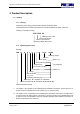
Operating and Installation Instructions FDB (Getriebebau NORD) 3. Product Description 3.1 Labelling 3.1.1 Lettering The lettering of the spring-pressure brake includes all important data. These data and the contractual provisions for the brakes establish the limits of their use. Lettering on the brake housing: 103V 12 09 40 Braking torque in Nm Year of manufacture Month of manufacture Operating voltage (DC) in Volt 3.1.
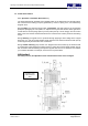
Operating and Installation Instructions FDB (Getriebebau NORD) 3.2 Technical Information 3.2.1 Operation of the Brake (Illustration 3.1) The electromagnetically released spring-applied brakes of the FDB series are fail-safe brakes, this means that the braking torque is generated by means of spring force, and released by magnetic force. During braking, the pressure springs (item 4, illustration 3.1) apply pressure to the armature plate (item 2) trapping the rotor (item 3.1 / 3.
Operating and Installation Instructions FDB (Getriebebau NORD) Brake type N (Illustration 3.1 top) The standard type of the spring-pressure brake is delivered with a fixed braking torque MbN. Via the number of springs (item 4), this torque can be varied as per 3.2.2.1. Brake type C (Illustration 3.1 bottom) The braking torque for this brake type with central adjusting ring (item 10) is also adjustable via the number of springs as per 3.2.2.1 similar to type N.
Operating and Installation Instructions FDB (Getriebebau NORD) 3.2.2.3 Dimensions, masses, attachment (illustration 3.2) Illustration 3.2: Main dimensions of the brake Size a (air gap) and s (rotor size): see 3.2.2.
Operating and Installation Instructions FDB (Getriebebau NORD) Masses [kg] Size Brake without manual release and flange Attachment dimensions [mm] Manual release Flange Hole circle (Bore qty.) x Thread depth with-out / threadwith friction nom.-Ø plate Øe1 ±0,1 Tightening torque [Nm] Adjusting dimensions [mm] Fastening screws Threaded ring (design C) Manual release e1 k1 b2 / b1 MA p…pmax y 08 1,10 0,05 0,20 72 (3 x) M4 6 / 9,5 3 3...
Operating and Installation Instructions FDB (Getriebebau NORD) 3.2.2.5 Friction work, friction capacity Max. permissible friction capacity** [J/h] Size Max. permissible friction work / braking [J] Max. permissible friction capacity** [J/h] Working brake PRmax 288 x 103 360 x 103 468 x 103 576 x 103 720 x 103 900 x 103 1080 x 103 1260 x 103 1440 x 103 1620 x 103 08 10 13 15 17 20 23 26 30 40 Max.
Operating and Installation Instructions FDB (Getriebebau NORD) 3.2.2.7 Switching times Nominal braking torque [Nm] Size Separating time [ms] Response delay [ms] Linkage time [ms] switched on d.c. side 08 10 13 15 17 20 23 26 30 40** Response delay [ms] Linkage time [ms] switched on a.c.
Operating and Installation Instructions FDB (Getriebebau NORD) 4. Assembly 4.1 Mechanical Installation 4.1.1 Prerequisites and Preparation - - When unpacking the spring-applied brake check for damage, and missing parts (according to delivery note). Complaints regarding damages in transit have to be immediately made with the supplier, complaints of missing parts or short supply have to be made with PRECIMA (also refer to 2.5).
Operating and Installation Instructions FDB (Getriebebau NORD) The rotor is fixed to the motor shaft and revolves with the motor shaft and brakes the shaft when power is removed from the brake: - Insert the first circlip (item 14) into the rear radial groove of the shaft Insert the feather key (item 15) into the axial groove of the shaft Push the toothed hub (item 6.1) or the hexagon hub (item 6.
Operating and Installation Instructions FDB (Getriebebau NORD) - Tighten the fastening screws with the tightening torque according to 3.2.2.3 - Position the O-ring (item 13; only for brakes with option “Operating noise-damped”) Position the dust ring (item 9; only for brakes with option S ) Screw the manual release lever (item 5.
Operating and Installation Instructions FDB (Getriebebau NORD) Illustration 4.2: Assembly of the manual release (partial sectional view) 5. Operation 5.1 Brake in Operation 5.1.1 Commissioning Before commissioning the brake, a functional test has to be carried out. This can normally be carried out together with the motor & brake attached. For possible malfunctions refer to: 5.2.
Operating and Installation Instructions FDB (Getriebebau NORD) + at least every two years + according to specifications made by the customer + use shorter intervals in case of frequent emergency stops Holding brake: Furthermore, check the rotor size s after a number of re-adjustments of the air gap a (see 5.1.3). A suitable control interval results from the relation of the difference sneu – smin to difference anenn – amax considering the respective tolerances. 5.1.3 Maintenance 5.1.3.
Operating and Installation Instructions FDB (Getriebebau NORD) 5.1.3.2 Replace the rotor When the minimum rotor size smin according to 3.2.2.4 is reached, a re-adjustment of the air gap “a” is no longer possible and the rotor has to be replaced. An operative readiness of the brake in certain cases falling below the minimum rotor size does not change the above statement; in such a case “a proper use” is no longer existing.
Operating and Installation Instructions FDB (Getriebebau NORD) 6. Disassembly / Exchange 6.1 Removing the Brake Removing the brake is the reverse of the assembly must only be done with the brake and motor being switched off, de-energised and torque-free. Î Danger! The disassembly of the brake will result in a suspension of its holding torque. No risks must be takes with said suspension! 6.
Operating and Installation Instructions FDB (Getriebebau NORD) Illustration 6.1: Spare parts (Sectional view) Item 1.1 1.2 2 3.1 3.2 4 5 5.1 6.1 Version 08.2011 Designation Magnet part cpl. design N Magnet part cpl. design C Armature plate Rotor cpl. (Alu design) Rotor cpl. (plastic design) Springs Manual release cpl. Manual release lever Hub for rotor 3.1 Item 6.2 7 8 9 10 11 12 13 Designation Hub for rotor 3.