
Manual


3 Options
BU 0200 GB-4411 Subject to technical alterations 105
3.5.4 I/O Extension, SK TU4-IOE, ...-M12
The internal I/O units can record sensor and actuator signals. These can be used for a drive function or
forwarded to a host bus system (e.g. Profibus or CANopen). Up to two I/O modules (also combinations: 1 x
SK CU4-IOE and 1 x SK TU4-IOE) can be connected to an inverter (up to firmware version V1.0 R1 of the
I/O extension and firmware version V1.1 R2 of the frequency inverter, only one I/O extension is possible for
each frequency inverter.).
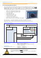
The I/O extension SK TU4-IOE- TI4-TU-BUS
Adapter Unit. Communication with the frequency inverter(s) is via
the system bus. All connections (power supply, system bus,
sensors,...) are made via the terminal block of the BUS Adapter
Unit. The M12-versions of the I/O - extension (SK TU4-IOE-M12)
also provide M12 connections for each of the digital inputs and
outputs on the front side.
4x digital inputs
2x analog inputs
2x digital outputs
1x analog output
Status LEDs: BG status, BG fault
Additional LEDs, M12 version: Dig. In 1 - 4, Dig. Out 1 - 2
DIP switches for selection
0 - 10V, -10 - 10V, 0 - 20mA, 4 - 20mA
DIP switches for: addressing, bus termination
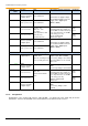
Control connections SK TU4-IOE(-…)
The double spring terminal block of the BUS -Adapter Unit is colour coded to indicate the three different
potential levels.
A separate voltage source should be used to supply the DOs. However, it is also possible to implement the
supply of the DOs by bridging the 24V 2 and 0V 2 with one of the terminals of the system bus level (24V and
0V). However, in this case it should be noted that this produces an increased risk of errors on the bus
cables.
The sensors and actuators are connected to the terminal block. Alternatively, the SK TU4-IOE-M12 module
enables connection of the digital I/Os via the M12 round plug connectors (Socket, 5-pin, A-coded) on the
front of the module.
Double use of the inputs via the terminal block and the M12 round plug should be avoided.
Analog IOs
System bus level and digital inputs
Digital outputs
10V-A
AIN1+
AIN1-
0V-A
AOUT
24V
24V
(as11)
0V
0V
DIN 1
0V
24V
(as11)
DIN 2
0V
24V
(as11)
24V 2
DO 1
0V 2
1
3
5
7
9
11
13
15
17
19
21
23
25
27
29
31
33
35
2
4
6
8
10
12
14
16
18
20
22
24
26
28
30
32
34
36
10V-A
AIN2+
AIN2-
0V-A
PE
24V
(as11)
Sys +
Sys -
0V
DIN 3
0V
24V
(as11)
DIN 4
0V
24V
(as11)
0V 2
DO 2
0V 2
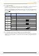
Terminal block of the bus Adapter Unit
SK TI4-TU-BUS and assignment of functions
Potential level: Analog I/O
Potential level: System bus
Potential level: DOs