
Manual


SK 200E Manual for frequency inverters
120 Subject to technical alterations BU 0200 GB-4411
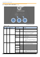
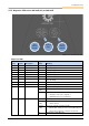
Details of the control connections
Terminal/
Name
Function
Data
Description / wiring suggestion
Parameter
1 24V-B
2
24V bus supply
(Field bus)
24VDC -/+20%
protected against reverse
polarity
Max. permissible current
load: 3A
Supply voltage for the DeviceNet
controller / field bus
-
3 CAN+
(incoming)
4
(outgoing)
Bus +
DeviceNet H
RS485 transfer
technology
The use of a twisted, shielded two-
wire cable is strongly
recommended
-
5 CAN-
(incoming)
6
(outgoing)
Bus -
DeviceNet L
-
7 0V-B
8
Data ground Bus
BUS reference potential
-
9 SHLD
Bus shield
-
10 PE
PE-Bus
-
Potential separation
11 24V
12
13
24V supply
(module, system bus level)
24VDC -/+20%
protected against reverse
polarity
Max. permissible current
load: 3A
Connection for module supply
voltage and 24V source for the
digital inputs (DIN1 to DIN4)
-
15 0V
17
18
GND
Reference potential
for digital signals
-
14 Sys+
System bus
data cable +
System bus
interface
-
16 Sys-
System bus
data cable -
-
19 DIN1
Digital input 1
(I/O DeviceNet DIN1)
Low 0V ... 5V
High 15V ... 30V
R
i
= 8.1k
Input capacitance 10nF
Scan rate 1ms
Each digital input has a reaction
time of 1ms
Inputs compliant with
EN 61131-2, Type 1
P174
20 DIN3
Digital input 3
(I/O DeviceNet DIN3)
P174