
Manual


SK 200E Manual for frequency inverters
162 Subject to technical alterations BU 0200 GB-4411
5.4.3 Bus structure and technology
The AS interface network can be set up in any desired form. Linear, star, ring and tree structures are
possible. An existing network can be expanded by further slaves at any time. Up to 31 standard slaves (i.e.
a maximum of 124 binary sensors and 124 binary actuators) or 62 A/B slaves (i.e. a maximum of 248 binary
sensors and 248 binary actuators) can be connected to an AS interface network or an AS interface master.
Each AS interface slave has its own a
slave with the aid of an addressing device, or is transferred to the slave by means of a command from the
AS interface master. Each slave address may only be assigned once.
Usually the AS interface master is a part or component of the control unit and forms the interface between
the control unit and the connected slaves. An AS master communicates independently and exchanges data
with the connected AS-i slave options. Normal network components may not be used in an AS interface
network. Only a special AS interface mains unit may be used for the power supply of each AS interface
strand. This AS interface power supply is connected directly to the yellow standard cable (ASI+ and ASI-
cable) and should be located as close as possible to the AS-i master in order to keep the voltage drop as
small as possible.
NOTE
It is essential that the PE connection of the AS interface mains unit (if present) is earthed.
The brown ASi+ and the blue ASi- wire from of the AS interface cable must not be earthed.
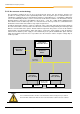
AS Interface
Master
AS Interface
mains unit
Sensors
Aktuators
Sensors
Aktuators
AS Interface
Slave (SK 2xxE)
AS Interface
Slave (SK 2xxE)
AS-Interface
yellow cable
Control unit /
Automation device
observe max.
power load