
Manual


6 Parameterisation
BU 0200 GB-4411 Subject to technical alterations 239
Parameter
{Factory setting}
Setting value / Description / Note
Device
Supervisor
Parameter
set
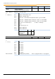
P161 [-01]
...
[-09]
Filter time
(Filter time)
0 ... 400.00 ms
{ [-01] = 100 }
{ [-02] = 100 }
{ [-03] = 0 }
{ [-04] = 2 }
{ [-05] = 2 }
{ [-06] = 2 }
{ [-07] = 2 }
{ [-08] = 0 }
{ [-09] = 0 }
The analog and digital inputs are read cyclically every 250µs, this results in an input uncertainty
of 0.25ms. In order to eliminate bounce and smooth the input signals, the information which is
read in is passed through a filter routine. The filter time can be parameterised
If, for example, a filter time of 1 ms is parameterised for a digital input, the input signal is
delayed by approx. 1...1.25ms.
The parameterisation of the filter time for the analog outputs is used to round off signal jumps.
[-01] = AIN1
[-02] = AIN2
[-03] = AOUT
[-04] = DIN1
[-05] = DIN2
[-06] = DIN3 (only SK TU4-IOE)
[-07] = DIN4 (only SK TU4-IOE)
[-08] = DOUT1 (only SK TU4-IOE)
[-09] = DOUT2 (only SK TU4-IOE)
P162
Send broadcast
(Send broadcast)
0 ... 1
{ 0 }
Activation of this parameter (setting On 1 ) switches the I/O extension module into broadcast
mode and thus enables simultaneous access by up to four frequency inverters. Each frequency
inverter evaluates the information from the I/O extension individually.
The addressing of the module (DIP switches) is no longer taken into account.
0 = Off
1 = On
NOTE: The data received by the I/O module is subject to an OR logic. If several frequency
inverters are linked to the digital outputs of the module, the relevant output is set to
"High" as soon as an inverter accesses it. The analog outputs behave in a similar
manner. Here, the highest value has priority.
P163
AOut Inverse
(Invert analog output)
0 ... 1
{ 0 }
The function of the analog output can be inverted
0 = No inversion
1 = Analog output signal is inverted