
Manual


SK 200E Manual for frequency inverters
74 Subject to technical alterations BU 0200 GB-4411
3.2.2 Installation of external technology units SK TU4-…
WARNING
Installations should only be made by qualified personnel, in strict compliance with the
warning and safety information.
Modules must not be inserted or removed unless the device is free of voltage. The slots
can only be used for the intended modules.
Installation of the technology unit at a location away from the frequency inverter is possible
with an additional wall-mounting kit SK TIE4-WMK-TU.
In combination with the connection unit SK TI4-TU-MSW, SK TI4-TU-BUS(-C) or SK TI4-TU-NET(-C) the
SK TU4--C) technology units form a discrete functional unit. This can be attached to the SK 2xxE
frequency inverter or installed separately by means of the optional SK TIE4-WMK-TU wall-mounting kit. In
order to ensure reliable operation, cable lengths in excess of 20m between the module and the frequency
inverter should be avoided.
3.2.2.1 Dimensions
As a functional unit in combination with an SK TI4-TU- TU4-
dimensions.
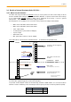
3.2.2.2 Connection unit SK TI4-TU-xxx(-C)
Various cable glands closed by caps are located on the sides of the
maintenance switch and the BUS or mains connection unit.
The following holes are available for the cable glands:
2 x 1 M20 x 1.5 (at side)
4 M16 x 1.5 (underside)
2 M25 x 15 (at rear, without blank plugs)
The transparent screw connection at the top right (M20 x 1.5) (only SK TI4-TU-BUS(-C)) is used for access
to the diagnostic interface (RJ12 socket, interface RS232/RS485). The top left screw connector is not used.
136
91*
95
136
58
136
Fig.: SK TIE4-WMK-TU wall-mounting kit
Fig.: Functional unit SK TU4-… and SK TI4-TU-… with
wall-mounting kit SK TIE4-WMK-TU
* For SK TU4--M12 modules:
99 mm (without cover cap for M12 plug)
108 mm (with cover cap for M12 plug)
155
Thickness of material: approx. 3.5 mm
Example:
external BUS adapter unit SK TI4-TU-BUS