
Manual


3 Options
BU 0200 GB-4411 Subject to technical alterations 95
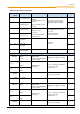
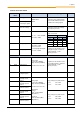
Control connection details
Terminal/
Name
Function
Data
Description / wiring suggestion
Parameter
44 24V
24V supply
24VDC ±25%
mA (according
to load on the digital
output)
Supply voltage connection for the
module
-
40 GND /0V
GND
Reference potential
-
C5 DIN
Digital input
Current consumption with
30V
DC
: 13mA
24V
DC
: 10mA
15V
DC
: 5.5 mA
Switching thresholds
ON: > approx. 8.5V
OFF: < approx. 7.5V
Digital input for DC brake switching
-
B5 DOUT
Digital output
-
compatible according to
EN61131-2
Low: 0V / <30mA
No current through brake
High: 24V / >70mA
Current through brake
Reporting of current status of the
mechanical brake
-
Potential isolation
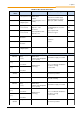
79 MB+
Brake control
Voltage:
Mains Brake
230V~ 205V=
400V~ 180V=
460/480V~ 205V=
Current: max. 0.5A
The module SK CU4-MBR
generates an output voltage on
Terminals MB+/MB- for control of
an electromechanical brake. This
depends on the supply voltage and
the connection of the supply cable
to the one-way (L1
E
) or bridge
rectification (L1
B
) of the module.
The assignment of the correct
brake coil voltage must be taken
into account in the selection.
(NOTE: this function is identical to
P434=1)
P107*,
P114*,
P505
80 MB-
Brake control
Potential isolation
L1
E
Mains connection
1st phase
Supply voltage L1:
± 10% AC,
max. 10A
Mains connection for one-way
rectification.
-
L1
E
-
L1
B
Mains connection
1st phase
Supply voltage L1:
± 10% AC,
max. 10A
Mains connection for bridge
rectification.
-
L1
B
-
L2/N
Mains connection
2nd phase
Connection of 2nd phase for mains
connection L1
E
or L1
B
.
-
L2/N
-
* Recommended setting (P107/P114) for NORD brakes: BRE5, 10, 40: 0.02s / BRE 20, 60, 100, 150: 0.03s