
Manual


SK 200E Manual for frequency inverters
96 Subject to technical alterations BU 0200 GB-4411
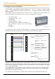
3.4.8 Setpoint converter, SK CU4-REL
The analog inputs of SK 2x0 E series frequency inverters and the optional mains units SK xU4-24V can only
process unipolar setpoin
(- CU4-REL
setpoint converter.
Two coupling relays are integrated into the module. These are controlled via the digital outputs of the
frequency inverter and can be used as openers or closers according to their connection.
+24V control voltage
2x Analog inputs (-
2x digital inputs
2x Relay outputs (each configured as changeovers)
Max. permissible continuous relay current 100mA
(30VDC)
incl. cable set
The terminal bar of the customer unit SK CU4-PBR- tential
separation max. 50VDC). On delivery, these are connected together with a plug-in jumper.
The bipolar analog signals must be connected to input terminals 114 or 116. Via the analog outputs
(Terminal 117 or 118) the signals which are transformed to 0...10V can be accessed and transferred to the
frequency inverter for further processing. In order to ensure the function of the analog signal converter, the
10V
DC
reference voltage of the frequency inverter must be wired to the reference potential of the setpoint
source(s) of the SK CU4-REL
Up to 2 digital signals can be transferred to the coupling relays from the frequency inverter. Regardless of
the wiring, both relays each provide the possibility of accessing an opening (NC) or a closing (NO) signal.
The module must be supplied with 24V
DC
.
To separate the two potential levels, the jumper (at the start of the series terminal) must be pulled out.
R21
R22
R24
R11
R12
R14
40
C2
C1
118
117
116
114
111
112
44
Relay 1
Connection of the 24V power
supply from the SK 2x0E
AOUT connection of the
SK CU4 to AIN of the SK 2x0E
24V
AGND / 0V
Connection to the terminal bar
of the SK CU4-REL-
10V REF.
DI1
AOUT1
R11 / R14 = NO
R11 / R12 = NC
SK CU4-
SK 2x0E-
Digital control IN of the SK CU4 via
DO from the SK 2x0E
AIN1
Connection for bipolar analog
signals
Potential level: Analog
Potential level: Digital / Relay
…
11
12*
44
1
16
14
…
40
3
AIN2
AOUT2
DI2
Relay 2
R21 / R24 = NO
R21 / R22 = NC
* Terminal 12 or Terminal 40
GND / 0V
Similar to illustration