
Manual


3 Options
BU 0200 GB-4411 Subject to technical alterations 97
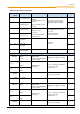
Control connection details
Terminal/
Name
Function
Data
Description / wiring suggestion
Parameter
44 24V
24V supply
24VDC ±25%
20mA
Connection of the supply voltage
for the module and the reference
potential of the analog signals
112 AGND/0V
Reference potential
for analogue signals
111 10V REF
+10V
Reference voltage
+10V, 5mA
Connection of reference voltage
from frequency inverter
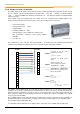
114 AIN1
Analog input 1
U= -
i
Resolution 10Bit
Signal IN
Signal OUT
Terminal
Value
Terminal
Value
114
-10V
117
+10V
114
+10V
117
0V
116
-10V
118
+10V
116
+10V
118
0V
The conversion of the analog
signals is inverted.
Assignment of the functions of the
analog input signals is made via
parameter P400[...] of the
frequency inverter.
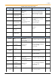
116 AIN2
Analog input 2
117 AOUT1
Analog output 1
Resolution: 10Bit
Precision: 0.25V
Load capacity with signal:
10mA
118 AOUT2
Analog output 2
Potential isolation
C1 DIN1
Digital input 1
Relay input:
Low: 0-5V (2.8kOhm)
High: 18-30V (1.6kOhm)
Reaction time max. 7ms
Assignment of the functions of the
analog output signals is made via
parameter P434[...] of the
frequency inverter.
C2 DIN2
Digital input 2
40 GND /0V
Reference potential
for digital signals
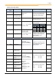
R14 R1 NO
Relay 1.1
Normally closed
contact
Relay input:
Low: 0-5V (2.8kOhm)
High: 18-30V (1.6kOhm)
Reaction time max. 7ms
Mechanical
lifetime:
1x10
8
(1 billion) OPS
(Operations)
Electrical:
3x10
5
(3 million) OPS
(Operations)
Relay (changeover) with function:
Closer: R11 / R14
Opener: R11 / R12
R12 R1 NC
Relay 1.2
Normally opened
contact
R11
Relay 1.3
Common contact
R24 R2 NO
Relay 2.1
Normally closed
contact
Relay (changeover) with function:
Closer: R21 / R24
Opener: R21 / R22
R22 R2 NC
Relay 2.2
Normally opened
contact
R21
Relay 2.3
Common contact