
User's Manual


9 (23)
2011-06-29
NUR-05W Implementation Guide v0.7
CONFIDENTIAL
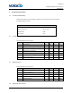
47 RF_OUT Bidirectional 50Ω RF output/input
48 GND Supply input Ground
49 RFU Bidirectional RFU, DNU (do not use)
50 GND Supply input Ground
3.3 Signal description
Signal name: GND Pin number(s): 15, 20-26, 28, 30, 33-46, 48, 50
These pins are used for grounding and to improve thermal performance. They should be connected to
Host board GND net.
Signal name: GPIO_X Pin number(s): 2-6
These pins are used as general purpose IO. They can be configured via SW API as input or output
ports. IO voltage level is 3.3V. GPIO_1, GPIO_2, GPIO_3 and GPIO_4 have current capability of 8mA
and GPIO_5 has 16mA.
Signal name: TST Pin number(s): 7
Pin is used for production testing purposes only. Should not be connected.
Signal name: RX Pin number(s): 8
Pin is used for module UART input signal. Logic level is 3.3V. If UART is used for communication pin
should be connected to Host MCU serial TX port.
Signal name: TX Pin number(s): 9
Pin is used for module UART output signal. Logic level is 3.3V. If UART is used for communication pin
should be connected to Host MCU serial RX port.
Signal name: USB_DN Pin number(s): 10
Pin is used as USB_D- device port. It is advised to use external ESD protection component if connected
to user accessible USB connector.
Signal name: USB_DP Pin number(s): 11
Pin is used as USB_D+ device port. It is advised to use external ESD protection component if connected
to user accessible USB connector.