
User's Manual


9
2016-03-18
NUR-10W HW Implementation Guide v1.4
3 PIN ASSIGNMENTS
3.1 PIN DESIGNATION
Figure 3. Through top view.
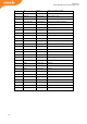
3.2 PIN MAPPING
Table 5. Pin mapping of the module.
Pin number
Signal name
Pin type
Description
1
RFU
Bidirectional
RFU (do not connect)
2
GPIO_5
Bidirectional
3.3V GPIO
3
GPIO_4
Bidirectional
3.3V GPIO
4
GPIO_3
Bidirectional
3.3V GPIO
5
GPIO_2
Bidirectional
3.3V GPIO
6
GPIO_1
Bidirectional
3.3V GPIO
7
ERASE
Input
DNU (do not use)
8
RX
Input
Data from Host to Module