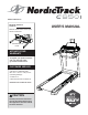
www.nordictrack.ca Model No. 25044C.0 Serial No. Write the serial number in the space above for reference. Serial Number Decal ACTIVATE YOUR WARRANTY To register your product and activate your warranty today, go to www.iconservice.ca. CUSTOMER SERVICE Call toll-free 1-888-936-4266 Mon.–Fri. 7:30 a.m.–4:30 p.m. ET (excluding holidays) or email us at customerservice@iconcanada.ca Please do not contact the store. CAUTION Read all precautions and instructions in this manual before using this equipment.
TABLE OF CONTENTS WARNING DECAL PLACEMENT . . . . . . . . . . . . . . . . . . . . . . . . . . . . . . . . . . . . . . . . . . . . . . . . . . . . . . . . . . . . . . . 2 IMPORTANT PRECAUTIONS . . . . . . . . . . . . . . . . . . . . . . . . . . . . . . . . . . . . . . . . . . . . . . . . . . . . . . . . . . . . . . . . . . 3 BEFORE YOU BEGIN. . . . . . . . . . . . . . . . . . . . . . . . . . . . . . . . . . . . . . . . . . . . . . . . . . . . . . . . . . . . . . . . . . . . . . . .
IMPORTANT PRECAUTIONS WARNING: To reduce the risk of burns, fire, electric shock, or injury to persons, read all important precautions and instructions in this manual and all warnings on your treadmill before using your treadmill. ICON assumes no responsibility for personal injury or property damage sustained by or through the use of this product. 1. It is the responsibility of the owner to ensure that all users of this treadmill are adequately informed of all warnings and precautions. 12.
19. Always stand on the foot rails when starting or stopping the walking belt. Always hold the handrails while using the treadmill. 26. When folding or moving the treadmill, make sure that the storage latch is holding the frame securely in the storage position. 20. When a person is walking on the treadmill, the noise level of the treadmill will increase. 27. Never insert any object into any opening on the treadmill. 21. Keep fingers, hair, and clothing away from the moving walking belt. 28.
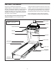
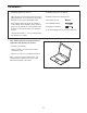
BEFORE YOU BEGIN Thank you for selecting the revolutionary NORDICTRACK® C 950I treadmill. The C 950I treadmill offers an impressive selection of features designed to make your workouts at home more effective and enjoyable. And when you’re not exercising, the unique treadmill can be folded up, requiring less than half the floor space of other treadmills. reading this manual, please see the front cover of this manual.
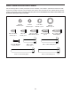
PART IDENTIFICATION CHART Use the drawings below to identify small parts used for assembly. The number in parentheses below each drawing is the key number of the part, from the PART LIST near the end of this manual. The number following the key number is the quantity used for assembly. Note: If a part is not in the hardware kit, check to see whether it is preattached. Extra parts may be included.
ASSEMBLY • Assembly requires two persons. • To identify small parts, see page 8. • Place all parts in a cleared area and remove the packing materials. Do not dispose of the packing materials until you finish all assembly steps. • Assembly requires the following tools: the included hex key one adjustable wrench • After shipping, there may be an oily substance on the exterior of the treadmill. This is normal.
2. Make sure that the power cord is unplugged. 2 Next, remove the tie securing the Upright Wire (81) to the front of the Base (94). A 81 81 Identify the Right Upright (90). Have a second person hold the Right Upright near the Base (94). See the inset drawing. Tie the wire tie (A) in the Right Upright (90) securely around the end of the Upright Wire (81). Then, insert the Upright Wire into the lower end of the Right Upright as you pull the other end of the wire tie through the Right Upright.
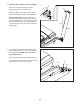
4. Hold the Right Upright (90) against the Base (94). Make sure not to pinch the Upright Wire (81). 4 7 Attach the Right Upright (90) and the Wheel (25) with two 3/8" x 2 1/4" Screws (7), a 3/8" x 1 1/4" Screw (63), a 3/8" x 1 3/4" Screw (62), and four 3/8" Star Washers (13) as shown; do not fully tighten the Screws yet. 13 Attach the Left Upright (not shown) in the same way. Note: There are no wires on the left side. 81 62 94 13 13 90 63 25 5.
6. Attach a Handrail (86) to the Right Upright (90) with two 5/16" x 2 1/2" Screws (28) and two 5/16" Star Washers (11) in the location shown; do not fully tighten the Screws yet. Make sure not to pinch the Upright Wire (81), and make sure that the wire is on the side of the Upright as shown. 6 28 11 86 E Attach the other Handrail (86) to the Left Upright (89) in the same way. Note: There are no wires on the left side. 28 89 11 Then, remove and discard the indicated screws (E). E 90 86 81 7.
8. Set the console assembly (F) face down on a soft surface to avoid scratching the console assembly. Remove and save the four 1/4" x 1/2" Screws (34). 8 34 F 34 9. Hold the console assembly (F) near the Pulse Crossbar (93). 9 F See the inset drawing. Connect the pulse wires (G, H). The connectors should slide together easily and snap into place. If they do not, turn one connector and try again. IF YOU DO NOT CONNECT THE CONNECTORS PROPERLY, THE CONSOLE MAY BECOME DAMAGED WHEN YOU TURN ON THE POWER.
10. Insert the Upright Wire (81) through the two indicated looped ties (I) on the console assembly (F). 10 Connect the Upright Wire (81) to the console wire (J). The connectors should slide together easily and snap into place. If they do not, turn one connector and try again. IF YOU DO NOT CONNECT THE CONNECTORS PROPERLY, THE CONSOLE MAY BECOME DAMAGED WHEN YOU TURN ON THE POWER. Then, remove the wire tie from the Upright Wire. F J I I 11.
12. Identify the Right and Left Trays (27, 36). 12 27 Attach the Trays (27, 36) to the Console Base (64) with eight #8 x 1/2" Screws (1); do not overtighten the Screws. 36 64 1 1 13. Carefully slide the Upright Crossbar (41) between the Left and Right Uprights (89, 90). Attach the Upright Crossbar with the four 5/16" x 3/4" Screws (4) that you removed in step 5 and four 5/16" Star Washers (11); start all four Screws, and then tighten them.
14. Identify the Right Handrail Cover (85). Set the Right Handrail Cover on the right Handrail (86). Start two #8 x 3/4" Truss Head Screws (14) into the bottom of the Handrail Cover; do not fully tighten the Screws. 14 79 Next, slide the Right Handrail Cover (85) forward until it rests against the console assembly (F). Then, tighten the two #8 x 3/4" Truss Head Screws (14); do not over tighten the Truss Head Screws.
16. Remove the 5/16" Nut (12) and the 5/16" x 1 3/4" Bolt (6) from the bracket on the Base (94). 16 Next, orient the Storage Latch (53) as shown. M Attach the lower end of the Storage Latch (53) to the bracket on the Base (94) with the 5/16" x 1 3/4" Bolt (6) and the 5/16" Nut (12). 53 Then, raise the Storage Latch (53) to a vertical position, and remove the tie (M). 12 94 17. Remove the 5/16" Nut (12) and the 5/16" x 2 1/4" Bolt (3) from the bracket on the Latch Crossbar (38).
. Firmly tighten the four 3/8" x 2 1/4" Screws (7), the two 3/8" x 1 3/4" Screws (62), and the two 3/8" x 1 1/4" Screws (63). Do not overtighten the Screws. 18 89 82 Set the Left Inner Base Cover (113) onto the lower end of the Left Upright (89). Then, slide the Left Base Cover (82) downward and press it onto the Left Inner Base Cover. 90 113 63 Next, set the Right Inner Base Cover (114) onto the lower end of the Right Upright (90).
HOW TO USE THE TREADMILL HOW TO CONNECT THE POWER CORD nominal 120-volt circuit capable of carrying 15 or more amps. To avoid overloading the circuit, do not plug other electrical devices, except for lowpower devices such as cell phone chargers, into the surge suppressor or into an outlet on the same circuit. IMPORTANT: If the treadmill is connected to an AFCI-equipped outlet and your circuit breaker trips repeatedly when the treadmill is used, see the front cover of this manual to purchase an arc filter.
CONSOLE DIAGRAM FEATURES OF THE CONSOLE To turn on the power, see page 21. To use the manual mode, see page 21. To use an onboard workout, see page 23. To use a custom-focus weight loss workout, see page 24. To connect your smart device to the console, see page 25. To connect your heart rate monitor to the console, see page 25. To use the sound system, see page 26. To use the settings mode, see page 26.
HOW TO TURN ON THE POWER HOW TO USE THE MANUAL MODE IMPORTANT: If the treadmill has been exposed to cold temperatures, allow it to warm to room temperature before you turn on the power. If you do not do this, you may damage the console displays or other electrical components. 1. Insert the key into the console. Plug in the power cord (see page 19). Next, locate the power switch on the treadmill frame near the power cord. Press the power switch into the reset position.
5. Change the incline of the treadmill as desired. To reset the displays, press the Stop button repeatedly, or remove the key and then reinsert the key. To change the incline of the treadmill, press the Incline increase and decrease buttons or one of the Quick Incline buttons. Each time you press one of the buttons, the treadmill will gradually adjust to the selected incline setting. 7. Measure your heart rate if desired.
HOW TO USE AN ONBOARD WORKOUT 8. Turn on the fan if desired. 1. Insert the key into the console. The fan features multiple speed settings and an auto mode. When the auto mode is selected, the speed of the fan will automatically increase and decrease as the speed of the walking belt increases and decreases. See HOW TO TURN ON THE POWER on page 21. 2. Enter your weight. See step 3 on page 21. Press the fan buttons repeatedly to select a fan speed or the auto mode, or to turn off the fan. 3.
5. Follow your progress with the displays. 4. Start the workout. See step 6 on page 22. If you select an onboard workout, the display will show the time remaining instead of the elapsed time. Press the Start button to start the workout. A moment after you press the button, the walking belt will begin to move. Hold the handrails and begin walking. 6. Measure your heart rate if desired. The workout will function in the same way as the manual mode (see pages 21 to 23). See step 7 on page 22. 7.
HOW TO CONNECT YOUR SMART DEVICE TO THE CONSOLE THE OPTIONAL CHEST HEART RATE MONITOR Whether your goal is to burn fat or to strengthen your cardiovascular system, the key to achieving the best results is to maintain the proper heart rate during your workouts. The optional chest heart rate monitor will enable you to continuously monitor your heart rate while you exercise, helping you to reach your personal fitness goals. To purchase a chest heart rate monitor, please see the front cover of this manual.
HOW TO USE THE SOUND SYSTEM HOW TO ADJUST THE CUSHIONING SYSTEM To play music or audio books through the console sound system while you exercise, plug a 3.5 mm male to 3.5 mm male audio cable (not included) into the jack on the console and into a jack on your MP3 player, CD player, or other personal audio player; make sure that the audio cable is fully plugged in. Note: To purchase an audio cable, see your local electronics store. Remove the key from the console and unplug the power cord.
HOW TO FOLD AND MOVE THE TREADMILL HOW TO FOLD THE TREADMILL HOW TO MOVE THE TREADMILL To avoid damaging the treadmill, adjust the incline to zero before you fold the treadmill. Then, remove the key and unplug the power cord. CAUTION: You must be able to safely lift 45 lbs. (20 kg) to raise, lower, or move the treadmill. Before moving the treadmill, fold it as described at the left. CAUTION: Make sure that the storage latch is locked in the storage position. Moving the treadmill may require two people.
MAINTENANCE AND TROUBLESHOOTING MAINTENANCE c. Check the power switch located on the treadmill frame near the power cord. If the switch protrudes as shown, the switch has tripped. To reset the power switch, wait for five minutes and then press the switch back in. Regular maintenance is important for optimal performance and to reduce wear. Inspect and properly tighten all parts each time the treadmill is used. Regularly clean the treadmill and keep the walking belt clean and dry.
SYMPTOM: The incline of the treadmill does not change correctly c. Your treadmill features a walking belt coated with high-performance lubricant. IMPORTANT: Never apply silicone spray or other substances to the walking belt or the walking platform unless instructed to do so by an authorized service representative. Such substances may deteriorate the walking belt and cause excessive wear. If you suspect that the walking belt needs more lubricant, see the front cover of this manual. a.
b. If the walking belt slips when walked on, first remove the key and UNPLUG THE POWER CORD. Using the hex key, turn both idler roller screws clockwise, 1/4 of a turn. When the walking belt is correctly tightened, you should be able to lift each edge of the walking belt 2 to 3 in. (5 to 7 cm) off the walking platform. Be careful to keep the walking belt centered. Then, plug in the power cord, insert the key, and carefully walk on the treadmill for a few minutes.
EXERCISE GUIDELINES Burning Fat—To burn fat effectively, you must exercise at a low intensity level for a sustained period of time. During the first few minutes of exercise, your body uses carbohydrate calories for energy. Only after the first few minutes of exercise does your body begin to use stored fat calories for energy. If your goal is to burn fat, adjust the intensity of your exercise until your heart rate is near the lowest number in your training zone.
SUGGESTED STRETCHES The correct form for several basic stretches is shown at the right. Move slowly as you stretch—never bounce. 1. Toe Touch Stretch Stand with your knees bent slightly and slowly bend forward from your hips. Allow your back and shoulders to relax as you reach down toward your toes as far as possible. Hold for 15 counts, then relax. Repeat 3 times. Stretches: Hamstrings, back of knees and back. 1 2. Hamstring Stretch Sit with one leg extended.
NOTES 33
PART LIST Key No. Qty. 1 2 3 4 5 6 7 8 9 10 11 12 13 14 15 16 17 18 19 20 21 22 23 24 25 26 27 28 29 30 31 32 33 34 35 36 37 38 39 40 41 42 43 44 45 46 47 48 49 50 20 31 1 6 4 1 4 4 4 1 10 6 8 8 3 1 2 1 4 2 2 2 4 2 4 2 1 4 1 4 2 2 6 4 13 1 8 1 6 2 1 1 1 1 1 2 1 4 1 1 Model No. 25044C.0 R1115A Description Key No. Qty.
Key No. Qty. 101 102 103 104 105 106 107 108 4 2 1 1 1 2 1 1 Description Key No. Qty. #3 x 1/4" Screw Fan Screw Tablet Holder Left Speaker Grill Right Speaker Grill Speaker Left Speaker Cover Right Speaker Cover 109 110 111 112 113 114 115 * 1 1 4 2 1 1 4 – Description Fan Controller Clamp Incline Leg Bushing Incline Leg Washer Left Inner Base Cover Right Inner Base Cover #8 x 1" Tek Screw User’s Manual Note: Specifications are subject to change without notice.
15 35 1 36 2 59 30 12 23 84 39 2 61 37 43 35 1 2 57 40 44 15 84 37 35 39 35 11 4 1 2 40 39 35 23 2 45 84 37 42 47 84 56 37 59 30 50 12 46 35 35 60 19 30 84 35 1 37 12 59 12 39 37 84 21 11 4 3 49 35 74 23 35 1 52 31 53 39 37 84 55 35 39 35 1 37 35 38 19 20 84 59 30 12 15 12 46 23 54 48 21 74 6 31 52 52 110 73 52 24 EXPLODED DRAWING A Model No. 25044C.
EXPLODED DRAWING B Model No. 25044C.
EXPLODED DRAWING C Model No. 25044C.
EXPLODED DRAWING D Model No. 25044C.
ORDERING REPLACEMENT PARTS To order replacement parts, please see the front cover of this manual.