nordictrack.ca Model No. NTL16915C.0 Serial No. Write the serial number in the space above for reference. Serial Number Decal ACTIVATE YOUR WARRANTY To register your product and activate your warranty today, go to iconservice.ca. CUSTOMER SERVICE Call toll-free 1-888-936-4266 Mon.–Fri. 7:30 a.m.–4:30 p.m. ET (excluding holidays) or email us at customerservice@iconcanada.ca Please do not contact the store. CAUTION Read all precautions and instructions in this manual before using this equipment.
TABLE OF CONTENTS WARNING DECAL PLACEMENT . . . . . . . . . . . . . . . . . . . . . . . . . . . . . . . . . . . . . . . . . . . . . . . . . . . . . . . . . . . . . . .2 IMPORTANT PRECAUTIONS. . . . . . . . . . . . . . . . . . . . . . . . . . . . . . . . . . . . . . . . . . . . . . . . . . . . . . . . . . . . . . . . . . 3 BEFORE YOU BEGIN. . . . . . . . . . . . . . . . . . . . . . . . . . . . . . . . . . . . . . . . . . . . . . . . . . . . . . . . . . . . . . . . . . . . . . . .6 PART IDENTIFICATION CHART.
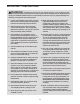
IMPORTANT PRECAUTIONS WARNING: To reduce the risk of burns, fire, electric shock, or injury to persons, read all important precautions and instructions in this manual and all warnings on your treadmill before using your treadmill. ICON assumes no responsibility for personal injury or property damage sustained by or through the use of this product. 1. It is the responsibility of the owner to ensure that all users of this treadmill are adequately informed of all warnings and precautions. 12.
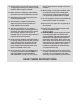
19. Always stand on the foot rails when starting or stopping the walking belt. Always hold the handrails while using the treadmill. able to safely lift 45 lbs. (20 kg) to move the treadmill. 26. When folding or moving the treadmill, make sure that the storage latch is holding the frame securely in the storage position. Do not operate the treadmill while it is folded. 20. When a person is walking on the treadmill, the noise level of the treadmill will increase. 21.
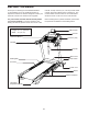
BEFORE YOU BEGIN Thank you for selecting the new NORDICTRACK® C 700 treadmill. The C 700 treadmill provides an impressive selection of features designed to make your workouts at home more effective and enjoyable. manual. To help us assist you, note the product model number and serial number before contacting us. The model number and the location of the serial number decal are shown on the front cover of this manual. For your benefit, read this manual carefully before you use the treadmill.
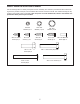
PART IDENTIFICATION CHART Use the drawings below to identify small parts used for assembly. The number in parentheses below each drawing is the key number of the part, from the PART LIST near the end of this manual. The number following the key number is the quantity used for assembly. Note: If a part is not in the hardware kit, check to see whether it is preattached. Extra parts may be included.
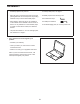
ASSEMBLY • Assembly requires two persons. • To identify small parts, see page 7. • Place all parts in a cleared area and remove the packing materials. Do not dispose of the packing materials until you finish all assembly steps. • Assembly requires the following tools: the included hex keys one Phillips screwdriver • After shipping, there may be an oily substance on the exterior of the treadmill. This is normal.
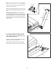
2. Make sure that the power cord is unplugged. 2 Remove the tie securing the Upright Wire (81) to the front of the Base (94). A 81 81 Next, identify the Right Upright (90). Have a second person hold the Right Upright near the Base (94). 90 See the inset drawing. Tie the wire tie (A) in the Right Upright (90) securely around the end of the Upright Wire (81). Then, insert the Upright Wire into the lower end of the Right Upright as you pull the other end of the wire tie through the Right Upright.
4. Hold the Right Upright (90) against the Base (94). Make sure not to pinch the Upright Wire (81). 4 Attach the Right Upright (90) with two 3/8" x 2 1/4" Screws (7), a 3/8" x 1 1/4" Screw (63), a 3/8" x 1 3/4" Screw (62), and four 3/8" Star Washers (13) as shown; do not fully tighten the Screws yet. 7 13 Attach the Left Upright (not shown) in the same way. Note: There are no wires on the left side. 81 94 63 5. Identify the Left and Right Base Covers (82, 83).
6. Identify the left handrail assembly (E). Attach the left handrail assembly to the Left Upright (89) with two 5/16" x 2 1/2" Screws (28) and two 5/16" Star Washers (11); do not fully tighten the Screws yet. 6 28 11 Then, remove and discard the indicated screw (F). E F 89 7. Insert the Upright Wire (81) into the bottom of the right handrail assembly (G) and out of the front as shown.
8. Tighten four #8 x 3/4" Screws (2) into the left and right handrail assemblies (E, G) and into the Left and Right Uprights (89, 90). 8 E 2 89 2 G 90 9. Set the Console Base (64) face down on a soft surface to avoid scratching the Console Base. If there are ties (H) securing the Pulse Crossbar (93) to the Console Base, remove the ties. 9 4 31 18 64 2 2 Remove and discard the four indicated screws (I). Then, remove the Pulse Crossbar (93).
10. Identify the Right and Left Trays (27, 36). 10 Attach the Trays (27, 36) to the Console Base (64) with eight #8 x 1/2" Screws (1); do not overtighten the Screws. 31 2 92 18 Reattach the Console Frame (18) with the four #8 x 3/4" Screws (2), the two #8 x 1" Screws (31), and the two Console Clamps (92) that you removed in step 9; do not overtighten the Screws. 2 92 1 1 31 27 1 1 64 36 11.
12. With the help of a second person, hold the console assembly (J) near the Handrails (86) (only one side is shown). 12 J Connect the ground wire (K) from the console assembly (J) to the Console Ground Wire (58) on the Pulse Crossbar (93). See the inset drawing. Connect the Upright Wire (81) to the console wire (L). The connectors should slide together easily and snap into place. If they do not, turn one connector and try again.
14. Attach the Pulse Crossbar (93) to the console assembly (J) with four #8 x 1/2" Screws (1); start all four Screws, and then tighten them. 14 J Then, firmly tighten the four 5/16" x 3/4" Screws (4). 4 4 93 1 15. Raise the Frame (56) to the upright position. Have a second person hold the Frame until step 17 is completed. 1 15 N Remove the two 5/16" x 3/4" Screws (4) from the Latch Crossbar (41). 41 M N 11 4 Orient the Latch Crossbar (41) as shown.
. Remove the 5/16" Nut (34) and the 5/16" x 1 3/4" Bolt (6) from the bracket on the Base (94). 16 O Next, orient the Storage Latch (53) as shown. Attach the lower end of the Storage Latch (53) to the bracket on the Base (94) with the 5/16" x 1 3/4" Bolt (6) and the 5/16" Nut (34) as shown. 53 Then, raise the Storage Latch (53) to a vertical position, and remove the tie (O). 34 17. Remove the 5/16" Nut (34) and the 5/16" x 2 1/4" Bolt (3) from the bracket on the Latch Crossbar (41).
18. Firmly tighten the four 3/8" x 2 1/4" Screws (7), the two 3/8" x 1 3/4" Screws (62), and the two 3/8" x 1 1/4" Screws (63). 18 89 82 Next, set the Left Inner Base Cover (99) onto the lower end of the Left Upright (89). Slide the Left Base Cover (82) downward and press it onto the Left Inner Base Cover. 99 63 Then, set the Right Inner Base Cover (100) onto the lower end of the Right Upright (90). Slide the Right Base Cover (83) downward and press it onto the Right Inner Base Cover.
HOW TO USE THE TREADMILL HOW TO CONNECT THE POWER CORD more amps. To avoid overloading the circuit, do not plug other electrical devices, except for lowpower devices such as cell phone chargers, into the surge suppressor or into an outlet on the same circuit. IMPORTANT: If the treadmill is connected to an AFCI-equipped outlet and your circuit breaker trips repeatedly when the treadmill is used, see the front cover of this manual to purchase an arc filter.
CONSOLE DIAGRAM FEATURES OF THE CONSOLE To turn on the power, see page 20. To use the manual mode, see page 20. To use an onboard workout, see page 22. To use a custom-focus weight loss workout, see page 23. To connect your tablet to the console, see page 24. To connect your heart rate monitor to the console, see page 24. To use the sound system, see page 25. To use the settings mode, see page 25.
HOW TO TURN ON THE POWER HOW TO USE THE MANUAL MODE IMPORTANT: If the treadmill has been exposed to cold temperatures, allow it to warm to room temperature before you turn on the power. If you do not do this, you may damage the console displays or other electrical components. 1. Insert the key into the console. Plug in the power cord (see page 18). Next, locate the power switch on the treadmill frame near the power cord. Press the power switch into the reset position.
5. Change the incline of the treadmill as desired. To reset the display, press the Stop button repeatedly, or remove the key and then reinsert the key. To change the incline of the treadmill, press the Incline increase and decrease buttons or one of the Quick Incline buttons. Each time you press one of the buttons, the treadmill will gradually adjust to the selected incline setting. 7. Measure your heart rate if desired.
8. Turn on the fan if desired. HOW TO USE AN ONBOARD WORKOUT The fan features multiple speed settings and an auto mode. When the auto mode is selected, the speed of the fan will automatically increase and decrease as the speed of the walking belt increases and decreases. 1. Insert the key into the console. See HOW TO TURN ON THE POWER on page 20. 2. Enter your weight. Press the fan buttons repeatedly to select a fan speed or the auto mode, or to turn off the fan. See step 3 on page 20. 3.
5. Follow your progress with the display. HOW TO USE A CUSTOM-FOCUS WEIGHT LOSS WORKOUT See step 6 on page 21. If you select an onboard workout, the display will show the time remaining instead of the elapsed time. 1. Insert the key into the console. See HOW TO TURN ON THE POWER on page 20. 6. Measure your heart rate if desired. 2. Enter your weight. See step 7 on page 21. See step 3 on page 20. 7. Turn on the fan if desired. 3. Set a calories or time goal. See step 8 on page 22.
HOW TO CONNECT YOUR TABLET TO THE CONSOLE 5. Disconnect your tablet from the console if desired. The console supports BLUETOOTH connections to tablets via the iFit Bluetooth Tablet app and to compatible heart rate monitors. Note: Other BLUETOOTH connections are not supported. To disconnect your tablet from the console, first select the disconnect option in the iFit Bluetooth Tablet app. Then, press and hold the Bluetooth Smart button on the console until the LED on the console turns solid green. 1.
HOW TO USE THE SOUND SYSTEM HOW TO ADJUST THE CUSHIONING SYSTEM To play music or audio books through the console sound system while you exercise, plug a 3.5 mm male to 3.5 mm male audio cable (not included) into the jack on the console and into a jack on your personal audio player; make sure that the audio cable is fully plugged in. Note: To purchase an audio cable, see your local electronics store. The treadmill features a cushioning system that reduces the impact as you walk or run on the treadmill.
HOW TO USE THE TABLET HOLDER IMPORTANT: The tablet holder is designed for use with most full-size tablets. Do not place any other electronic device or object in the tablet holder. Tablet Holder To insert a tablet into the tablet holder, set the bottom edge of the tablet in the tray. Then, pull the clip over the top edge of the tablet. Make sure that the tablet is firmly secured in the tablet holder. Reverse these actions to remove the tablet from the tablet holder.
HOW TO FOLD AND MOVE THE TREADMILL HOW TO FOLD THE TREADMILL HOW TO MOVE THE TREADMILL To avoid damaging the treadmill, adjust the incline to zero before you fold the treadmill. Then, remove the key and unplug the power cord. CAUTION: You must be able to safely lift 45 lbs. (20 kg) to raise, lower, or move the treadmill. Before moving the treadmill, fold it as described at the left. CAUTION: Make sure that the latch knob is locked in the storage position. Moving the treadmill may require two people. 1.
MAINTENANCE AND TROUBLESHOOTING MAINTENANCE b. After the power cord has been plugged in, make sure that the key is inserted into the console. Regular maintenance is important for optimal performance and to reduce wear. Inspect and properly tighten all parts each time the treadmill is used. Replace any worn parts immediately. c. Check the power switch located on the treadmill frame near the power cord. If the switch protrudes as shown, the switch has tripped.
SYMPTOM: The incline of the treadmill does not change correctly c. Your treadmill features a walking belt coated with high-performance lubricant. IMPORTANT: Never apply silicone spray or other substances to the walking belt or the walking platform unless instructed to do so by an authorized service representative. Such substances may deteriorate the walking belt and cause excessive wear. If you suspect that the walking belt needs more lubricant, see the front cover of this manual. a.
b. I f the walking belt slips when walked on, first remove the key and UNPLUG THE POWER CORD. Using the hex key, turn both idler roller screws clockwise, 1/4 of a turn. When the walking belt is correctly tightened, you should be able to lift each edge of the walking belt 2 to 3 in. (5 to 7 cm) off the walking platform. Be careful to keep the walking belt centered. Then, plug in the power cord, insert the key, and walk on the treadmill for a few minutes. Repeat until the walking belt is properly tightened.
EXERCISE GUIDELINES Burning Fat—To burn fat effectively, you must exercise at a low intensity level for a sustained period of time. During the first few minutes of exercise, your body uses carbohydrate calories for energy. Only after the first few minutes of exercise does your body begin to use stored fat calories for energy. If your goal is to burn fat, adjust the intensity of your exercise until your heart rate is near the lowest number in your training zone.
SUGGESTED STRETCHES The correct form for several basic stretches is shown at the right. Move slowly as you stretch—never bounce. 1. Toe Touch Stretch 1 Stand with your knees bent slightly and slowly bend forward from your hips. Allow your back and shoulders to relax as you reach down toward your toes as far as possible. Hold for 15 counts, then relax. Repeat 3 times. Stretches: Hamstrings, back of knees and back. 2. Hamstring Stretch Sit with one leg extended.
NOTES 33
PART LIST Key No. Qty. 1 2 3 4 5 6 7 8 9 10 11 12 13 14 15 16 17 18 19 20 21 22 23 24 25 26 27 28 29 30 31 32 33 34 35 36 37 38 39 40 41 42 43 44 45 46 47 18 37 1 6 2 1 4 1 2 9 10 1 8 18 3 1 2 1 4 2 2 2 4 2 2 2 1 4 1 4 2 2 6 6 13 1 6 4 6 2 1 1 1 1 1 2 1 Model No. NTL16915C.0 R0517A Description Key No. Qty.
Key No. Qty. 95 96 97 98 1 1 2 1 Description Key No. Qty. Right Inside Handrail Cover Right Outside Handrail Cover Base Pad Tablet Holder 99 100 101 * 1 1 2 – Description Left Inner Base Cover Right Inner Base Cover 3/8" Washer User’s Manual Note: Specifications are subject to change without notice. For information about ordering replacement parts, see the back cover of this manual. *These parts are not illustrated.
35 1 15 39 2 59 30 34 23 35 1 36 40 2 61 37 2 43 39 57 35 35 15 11 4 44 1 37 39 2 40 35 23 42 2 45 37 59 30 34 47 35 46 1 12 35 19 30 34 35 39 60 56 37 34 59 21 1 35 3 51 23 35 4 49 39 11 53 37 10 50 55 39 1 35 41 35 19 34 35 20 15 10 54 6 51 21 37 59 30 34 48 46 23 50 10 73 84 10 24 EXPLODED DRAWING A Model No. NTL16915C.
EXPLODED DRAWING B Model No. NTL16915C.
EXPLODED DRAWING C Model No. NTL16915C.
EXPLODED DRAWING D Model No. NTL16915C.
ORDERING REPLACEMENT PARTS To order replacement parts, please see the front cover of this manual.