www.nordictrack.ca Model No. NTL19814C.0 Serial No. Write the serial number in the space above for reference. Serial Number Decal ACTIVATE YOUR WARRANTY To register your product and activate your warranty today, go to www.iconservice.ca. CUSTOMER SERVICE Call toll-free 1-888-936-4266 Mon.–Fri. 7:30 a.m.–4:30 p.m. ET (excluding holidays) or email us at customerservice@iconcanada.ca Please do not contact the store. CAUTION Read all precautions and instructions in this manual before using this equipment.
TABLE OF CONTENTS WARNING DECAL PLACEMENT . . . . . . . . . . . . . . . . . . . . . . . . . . . . . . . . . . . . . . . . . . . . . . . . . . . . . . . . . . . . . . .2 IMPORTANT PRECAUTIONS. . . . . . . . . . . . . . . . . . . . . . . . . . . . . . . . . . . . . . . . . . . . . . . . . . . . . . . . . . . . . . . . . . 3 BEFORE YOU BEGIN. . . . . . . . . . . . . . . . . . . . . . . . . . . . . . . . . . . . . . . . . . . . . . . . . . . . . . . . . . . . . . . . . . . . . . . .7 PART IDENTIFICATION CHART.
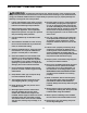
IMPORTANT PRECAUTIONS WARNING: To reduce the risk of burns, fire, electric shock, or injury to persons, read all important precautions and instructions in this manual and all warnings on your treadmill before using your treadmill. ICON assumes no responsibility for personal injury or property damage sustained by or through the use of this product. 1. It is the responsibility of the owner to ensure that all users of this treadmill are adequately informed of all warnings and precautions. 12.
26. Never insert any object into any opening on the treadmill. 21. The treadmill is capable of high speeds. Adjust the speed in small increments to avoid sudden jumps in speed. 27. Inspect and properly tighten all part each time the treadmill is used. 22. The heart rate monitor is not a medical device. Various factors, including the user’s movement, may affect the accuracy of heart rate readings. The heart rate monitor is intended only as an exercise aid in determining heart rate trends in general. 28.
BEFORE YOU BEGIN Thank you for selecting the revolutionary NORDICTRACK® C 990 treadmill. The C 990 treadmill offers an impressive selection of features designed to make your workouts at home more effective and enjoyable. And when you’re not exercising, the unique treadmill can be folded up, requiring less than half the floor space of other treadmills. reading this manual, please see the front cover of this manual.
PART IDENTIFICATION CHART Use the drawings below to identify small parts used for assembly. The number in parentheses below each drawing is the key number of the part, from the PART LIST near the end of this manual. The number following the key number is the quantity used for assembly. Note: If a part is not in the hardware kit, check to see whether it is preattached. Extra parts may be included.
ASSEMBLY • Assembly requires two persons. • To identify small parts, see page 8. • Place all parts in a cleared area and remove the packing materials. Do not dispose of the packing materials until you finish all assembly steps. • Assembly requires the following tools: the included hex key one adjustable wrench • After shipping, there may be an oily substance on the exterior of the treadmill. This is normal.
2. Make sure that the power cord is unplugged. 2 Press a Base Cap (74) into each side of the Base (94). A 81 81 Next, remove the tie securing the Upright Wire (81) to the front of the Base (94). Identify the Right Upright (90). Have a second person hold the Right Upright near the Base (94). 90 See the inset drawing. Tie the wire tie (A) in the Right Upright (90) securely around the end of the Upright Wire (81).
4. Insert a Wheel Spacer (63) into a Front Wheel (62). Then, hold the Front Wheel inside the Right Upright (90), and insert a 3/8" x 4" Screw (7) with a 3/8" Star Washer (13) into the Right Upright and the Front Wheel. 4 Repeat this step on the left side of the treadmill (not shown). 90 13 5. Place a piece of packing material (E) under the right side of the Base (94). Hold the Right Upright (90) against the Base. Make sure not to pinch the Upright Wire (81).
6. R emove and save the four indicated 5/16" x 3/4" Screws (4). 6 4 Identify the Left and Right Base Covers (82, 83). Slide the Left Base Cover onto the Left Upright (89), and slide the Right Base Cover onto the Right Upright (90). Do not press the Base Covers into place yet. 89 4 82 90 83 7. Identify the left handrail assembly (F). Attach the left handrail assembly to the Left Upright (89) with two 5/16" x 2 1/2" Screws (28) and two 5/16" Star Washers (11); do not fully tighten the Screws yet.
8. Insert the Upright Wire (81) into the bottom of the right handrail assembly (H) and out of the end as shown. 8 28 Attach the right handrail assembly (H) to the Right Upright (90) with two 5/16" x 2 1/2" Screws (28) and two 5/16" Star Washers (11); do not fully tighten the Screws yet. Make sure not to pinch the Upright Wire (81). 11 H 81 G Then, remove and discard the indicated screw (G). 90 9.
10. Set the Console Base (64) face down on a soft surface to avoid scratching the Console Base. If there are ties (I) securing the Pulse Crossbar (93) to the Console Base, remove the ties. 10 2 4 2 64 18 2 Remove and discard the four indicated screws (J). Then, remove the Pulse Crossbar (93). J Remove and save the four 5/16" x 3/4" Screws (4) and the six #8 x 3/4" Screws (2). Then, lift out the two Console Clamps (92) and the Console Frame (18). 92 4 I 93 2 I 11.
12. IMPORTANT: To avoid damaging the Pulse Crossbar (93), do not use power tools and do not overtighten the #10 x 3/4" Screws (9). 12 9 5 Orient the Pulse Crossbar (93) as shown. Attach the Pulse Crossbar to the Handrails (86) with two #10 x 3/4" Screws (9) and two #10 Star Washers (5); start both Screws, and then tighten them. Make sure not to pinch the Upright Wire (81). 28 93 86 9 5 Then, firmly tighten the four 5/16" x 2 1/2" Screws (28). 86 28 81 13.
14. Set the console assembly (K) on the brackets on the Handrails (86); do not pinch any wires. 14 Attach the console assembly (K) with the four 5/16" x 3/4" Screws (4) that you removed in step 10 and four 5/16" Star Washers (11); do not fully tighten the Screws yet. K 86 86 M Next, insert the excess Upright Wire (81) into the console assembly (K). Then, pull the two ties (M) tight against the Upright Wire and cut off the ends of the ties. 81 11 11 4 4 15.
. Attach the Tray (73) to the Upright Crossbar (41) with four #8 x 3/4" Screws (2); start all four Screws, and then tighten them. 17 73 2 18. Firmly tighten the six 3/8" x 4" Screws (7) (only one side is shown). 2 41 18 Then, press the Left Base Cover (82) and the Right Base Cover (83) onto the Base (94).
19. Note: If you assemble the treadmill on a smooth surface, it may roll forward during this step. 19 Raise the Frame (56) to the upright position. Have a second person hold the Frame until step 21 is completed. Q Remove the two 5/16" x 3/4" Screws (4) from the Latch Crossbar (38). 38 O Q 11 4 Orient the Latch Crossbar (38) as shown. Make sure that the “This side toward belt” sticker (O) is facing the treadmill.
21. Remove the 5/16" Nut (12) and the 5/16" x 2 1/4" Bolt (3) from the bracket on the Latch Crossbar (38). 21 12 Align the upper end of the Storage Latch (53) with the bracket on the Latch Crossbar (38), and insert the 5/16" x 2 1/4" Bolt (3) through the bracket and the Storage Latch. This will push a spacer (R) out of the other end; discard the spacer.
HOW TO USE THE TREADMILL HOW TO CONNECT THE POWER CORD nominal 120-volt circuit capable of carrying 15 or more amps. To avoid overloading the circuit, do not plug other electrical devices, except for lowpower devices such as cell phone chargers, into the surge suppressor or into an outlet on the same circuit. IMPORTANT: If the treadmill is connected to an AFCI-equipped outlet and your circuit breaker trips repeatedly when the treadmill is used, see the front cover of this manual to purchase an arc filter.
CONSOLE DIAGRAM FEATURES OF THE CONSOLE You can even listen to your favorite workout music or audio books with the console’s sound system while you exercise. The treadmill console offers an impressive array of features designed to make your workouts more effective and enjoyable. When you use the manual mode, you can change the speed and incline of the treadmill with the touch of a button. As you exercise, the console will display instant exercise feedback.
814 HOW TO TURN ON THE POWER HOW TO USE THE MANUAL MODE IMPORTANT: If the treadmill has been exposed to cold temperatures, allow it to warm to room temperature before you turn on the power. If you do not do this, you may damage the console displays or other electrical components. 1. Insert the key into the console. Plug in the power cord (see page 20). Next, locate the power switch on the treadmill frame near the power cord. Press the power switch into the reset position.
4. Change the incline of the treadmill as desired. The My Trail tab will show a track that represents 1/4 mile (400 m). As you exercise, the flashing rectangle will show your progress. The My Trail tab will also show the number of laps you complete. To change the incline of the treadmill, press the Incline increase and decrease buttons or one of the numbered incline buttons. Each time you press one of the buttons, the treadmill will gradually adjust to the selected incline setting.
6. Measure your heart rate if desired. 8. When you are finished exercising, remove the key from the console. You can measure your heart rate using either the handgrip heart rate monitor or an optional chest heart rate monitor (see page 28 for information about the optional chest heart rate monitor). Note: The console is compatible with BLUETOOTH® Smart heart rate monitors. Step onto the foot rails, press the Stop button, and adjust the incline of the treadmill to zero.
During the workout, the profiles on the speed and incline tabs Current Segment will show your progress. The walking belt will begin to move at the speed setting for the first segment of the workout. When the next segment of the workout begins, the treadmill will automatically adjust to the speed and incline settings for the next segment. 4. Follow your progress with the displays. The workout will continue in this way until the last segment ends. The walking belt will then slow to a stop. 7.
3. Select a pulse workout. The workout will continue until you reach the goal that you set. The walking belt will then slow to a stop. To select a pulse workout, press the Heart Rate button repeatedly until the desired workout appears in the display. Note: The calorie goal is an estimate of the number of calories that you will burn during the workout. The actual number of calories that you burn will depend on various factors such as your weight. 4. Enter your maximum heart rate.
HOW TO USE AN IFIT WORKOUT 5. Start the workout. Note: To use an iFit workout, you must have access to a wireless network (see pages 28 to 30). An iFit account is also required. Go to www.iFit.com to register for an iFit account. See step 3 on page 24. During some workouts, an audio coach may guide you through your workout. 1. Insert the key into the console. To stop the workout at any time, press the Stop button. The time will begin to flash in the display.
HOW TO USE THE SOUND SYSTEM HOW TO CHANGE CONSOLE SETTINGS To play music or audio books through the console sound system while you exercise, plug a 3.5 mm male to 3.5 mm male audio cable (not included) into the jack on the console and into a jack on your MP3 player, CD player, or other personal audio player; make sure that the audio cable is fully plugged in. Note: To purchase an audio cable, see your local electronics store.
Units—The selected unit of measurement will appear in the matrix. To change the unit of measurement, press the Enter button. To view distance in miles, select ENGLISH. To view distance in kilometers, select METRIC. The WiFi–Advanced option will allow you to set up a wireless network connection using your computer, smart phone, tablet, or other Wi-Fi device. See step 6 on page 30 for instructions.
5. Use WiFi–Advanced to set up a wireless connection. A list of networks will appear in the matrix. Press the up and down buttons to highlight the desired network. Then, press the Enter button. Note: Do not select IFIT_SETUP. This option will allow you to set up a wireless network connection using your computer, smart phone, tablet, or other Wi-Fi device. Note: The time display will show the number of the currently-selected access point.
HOW TO ADJUST THE CUSHIONING SYSTEM HOW TO USE THE TABLET HOLDER Remove the key from the console and unplug the power cord. In order to adjust the cushions, you may need to place the treadmill in the storage position (see HOW TO FOLD THE TREADMILL on page 32). You can use your tablet to browse media while you exercise. Place your tablet on the tablet holder and let the tablet holder hold your tablet in place.
HOW TO FOLD AND MOVE THE TREADMILL HOW TO FOLD THE TREADMILL HOW TO MOVE THE TREADMILL To avoid damaging the treadmill, adjust the incline to zero before you fold the treadmill. Then, remove the key and unplug the power cord. CAUTION: You must be able to safely lift 45 lbs. (20 kg) to raise, lower, or move the treadmill. Before moving the treadmill, fold it as described at the left. CAUTION: Make sure that the storage latch is locked in the storage position. Moving the treadmill may require two people.
MAINTENANCE AND TROUBLESHOOTING MAINTENANCE SYMPTOM: The power turns off during use Regular maintenance is important for optimal performance and to reduce wear. Inspect and properly tighten all parts each time the treadmill is used. a. Check the power switch (see drawing c at the left). If the switch has tripped, wait for five minutes and then press the switch back in. Regularly clean the treadmill and keep the walking belt clean and dry.
Locate the Reed Switch (52) and the Magnet (50) on the left side of the Pulley (49). Turn the Pulley until the Magnet is aligned with the Reed Switch. Make sure that the gap between the Magnet and the Reed Switch is about 1/8 in. (3 mm). If necessary, loosen the #8 x 3/4" Truss Head Screw (14), move the Reed Switch slightly, and then retighten the Truss Head Screw.
SYMPTOM: The walking belt is off-center or slips when walked on SYMPTOM: The iFit mode does not function correctly a. I f the walking belt is off-center, first remove the key and UNPLUG THE POWER CORD. If the walking belt has shifted to the left, use the hex key to turn the left idler roller screw clockwise 1/2 of a turn; if the walking belt has shifted to the right, turn the left idler roller screw counterclockwise 1/2 of a turn. Be careful not to overtighten the walking belt.
EXERCISE GUIDELINES Burning Fat—To burn fat effectively, you must exercise at a low intensity level for a sustained period of time. During the first few minutes of exercise, your body uses carbohydrate calories for energy. Only after the first few minutes of exercise does your body begin to use stored fat calories for energy. If your goal is to burn fat, adjust the intensity of your exercise until your heart rate is near the lowest number in your training zone.
SUGGESTED STRETCHES The correct form for several basic stretches is shown at the right. Move slowly as you stretch—never bounce. 1. Toe Touch Stretch Stand with your knees bent slightly and slowly bend forward from your hips. Allow your back and shoulders to relax as you reach down toward your toes as far as possible. Hold for 15 counts, then relax. Repeat 3 times. Stretches: Hamstrings, back of knees and back. 1 2. Hamstring Stretch Sit with one leg extended.
PART LIST Key No. Qty. 1 2 3 4 5 6 7 8 9 10 11 12 13 14 15 16 17 18 19 20 21 22 23 24 25 26 27 28 29 30 31 32 33 34 35 36 37 38 39 40 41 42 43 44 45 46 47 48 49 50 18 52 1 10 2 1 6 1 2 5 14 2 6 19 3 1 2 1 4 2 2 2 4 1 2 3 1 4 1 4 2 2 6 4 13 1 6 1 6 4 1 1 1 1 1 2 1 4 1 1 Model No. NTL19814C.0 R0715A Description Key No. Qty.
Key No. Qty. 101 102 103 104 1 2 2 2 Description Key No. Qty. Right Foot Pad Hood Post #8 x 1 3/4" Screw Bracket Clip 105 106 * 1 1 – Description Electronics Bracket French Warning Decal User’s Manual Note: Specifications are subject to change without notice. For information about ordering replacement parts, see the back cover of this manual. *These parts are not illustrated.
1 15 35 39 40 2 98 97 59 30 34 23 1 61 42 2 57 43 2 35 44 100 99 35 39 15 1 2 37 4 11 97 60 35 39 101 23 35 37 2 47 45 46 59 30 34 19 35 1 35 30 34 2 35 37 59 39 56 35 12 106 35 37 21 23 51 31 14 1 3 4 11 35 39 49 50 55 53 37 35 103 52 1 39 23 46 37 20 48 19 35 38 10 54 59 30 34 15 12 2 103 6 21 31 10 EXPLODED DRAWING A Model No. NTL19814C.
EXPLODED DRAWING B Model No. NTL19814C.
EXPLODED DRAWING C Model No. NTL19814C.
EXPLODED DRAWING D Model No. NTL19814C.
ORDERING REPLACEMENT PARTS To order replacement parts, please see the front cover of this manual.