Model No. 831.14595.1 Serial No. USER’S MANUAL Write the serial number in the space above for future reference. Serial Number Decal (Under Seat) QUESTIONS? As a manufacturer, we are committed to providing complete customer satisfaction. If you have questions, or if parts are damaged or missing, PLEASE CONTACT OUR CUSTOMER SERVICE DEPARTMENT DIRECTLY. Visit our website at www.proform.com new products, prizes, fitness tips, and much more! CALL TOLL-FREE: 1-888-825-2588 Mon.–Fri., 6 a.m.–6 p.m.
TABLE OF CONTENTS IMPORTANT PRECAUTIONS . . . . . . . . . . . . . . . . . . . . . . . . . . . . . . . . . . . . . . . . . . . . . . . . . . . . . . . . . . . . . . . . 3 BEFORE YOU BEGIN . . . . . . . . . . . . . . . . . . . . . . . . . . . . . . . . . . . . . . . . . . . . . . . . . . . . . . . . . . . . . . . . . . . . . . 4 PART IDENTIFICATION CHART . . . . . . . . . . . . . . . . . . . . . . . . . . . . . . . . . . . . . . . . . . . . . . . . . . . . . . . . . . . . . .5 ASSEMBLY . . . . . . . . . . . .
IMPORTANT PRECAUTIONS WARNING: To reduce the risk of serious injury, read the following important precautions before using the inversion table. 1. Read all instructions in this manual before using the inversion table. Use the inversion table only as described in this manual. the short knob is fully tightened before you use the inversion table. 13. Perform all activities on the inversion table in a slow, controlled manner. Aggressive exercise can cause the inversion table to tip over. 2.
BEFORE YOU BEGIN Thank you for selecting the NordicTrack® REVITALIZE™ INVERSION SYSTEM inversion table. The inversion table will increase your intervertebral dimension, decrease pressure on intervertebral discs, stretch and relax your muscles, and temporarily relieve back pain associated with the listed conditions. reading this manual, please see the front cover of this manual. To help us assist you, note the product model number and serial number before contacting us. The model number is 831.14595.1.
PART IDENTIFICATION CHART See the drawings below to identify small parts used in assembly. The number in parentheses by each drawing is the key number of the part, from the PART LIST on page 18. Note: Some small parts may have been preassembled. If a part is not in the parts bag, check to see if it has been preassembled.
ASSEMBLY • Tighten all parts as you assemble them, unless instructed to do otherwise. Make Assembly Easier This manual is designed to ensure that the inversion table can be assembled successfully by almost anyone. However, the inversion table has many parts, and the assembly process will take time. Most people find that if they set aside plenty of time, assembly goes smoothly. • As you assemble the inversion table, make sure that all parts are oriented as shown in the drawings.
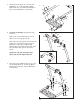
2. Attach the Left Base (1) to the Right Base (2) with two M10 x 80mm Button Bolts (52), four M10 Curved Washers (50), and two M10 Nylon Locknuts (65). 2 2 50 65 42 Attach another Foot (42) to the Right Base (2) with an M4 x 20mm Screw (71). 71 50 52 3. Attach the Support Leg (13) to the Center Base (3) with three M10 x 35mm Button Bolts (53) and three M10 Nylon Locknuts (65). 3 14 Attach the Base Plate (14) to the Center Base (3) with four M5 x 25mm Screws (59). 13 53 53 3 59 65 59 4.
5. Attach the Center Base (3) to the Left and Right Bases (1, 2) with four M10 x 80mm Button Bolts (52), four M10 Curved Washers (50), and four M10 Nylon Locknuts (65). 5 52 50 50 2 1 52 52 50 50 3 65 6. See the inset drawing. Identify the Center Frame (7). 6 32 65 70 Apply some of the included grease to both sides of the Left Large Spacer (31).
8. Attach the Top Cover (23) and the Bottom Cover (24) to the Center Frame (7) with two M4 x 15mm Screws (58) and an M4 x 30mm Screw (63). 8 58 23 24 63 7 Attach the Center Frame Extension (6) to the Center Frame (7) with two M10 x 53mm Button Bolts (49) and two M10 Nylon Locknuts (65). 58 49 6 65 9. Orient the Headrest Frame (9) and the Backrest Frame (8) as shown. Attach the Headrest Frame to the Backrest Frame with two M10 x 16mm Button Screws (54). 9 9 54 54 8 10.
11. See the left inset drawing. Identify the Top Tube (16), the Bottom Tube (17), and the Ankle Brace Tube (18); the Tubes have different lengths and holes in different positions. 11 Largest holes must be on top 16 18 17 16 Orient the Top Tube (16) and the Bottom Tube (17) so that the largest holes are on top (see the right inset drawing), and insert them into the indicated holes in the Leg Frame (10). Attach each Tube with an M4 x 15mm Screw (58).
14. Identify the two Rear Ankle Braces (34), which have holes in the indicated locations. 14 Slide a Rear Ankle Brace (34) onto the Ankle Brace Tube (18). Attach the Rear Ankle Brace with two M4 x 15mm Screws (58). Make sure that the Screws are tightened into the indicated holes in the Ankle Brace Tube. Next, press a 19mm Round Cap (45) into the Ankle Brace Tube, and attach the Round Cap with an M4 x 15mm Screw (58).
17. Attach the Headrest (20) to the Headrest Frame (9) with two M6 x 18mm Button Screws (55), an M6 x 55mm Button Screw (56), and three M6 Washers (62). 17 9 20 62 56 Attach the Backrest (21) to the Backrest Frame (8) in the same way. 55 62 21 8 18. Attach a Handle (12) to the Left Frame (4) with two M10 x 80mm Button Bolts (52), two M10 Curved Washers (50), and two M10 Nylon Locknuts (65). 18 12 Attach the other Handle (12) in the same way.
ADJUSTMENT This section explains how to adjust the inversion table. See DEVELOPING A PROGRAM on page 16 for important information about how to get the most benefit from the inversion table. Make sure that all parts are properly tightened each time you use the inversion table. Replace any worn parts immediately. The inversion table can be cleaned with a damp cloth and a mild, non-abrasive detergent. Do not use solvents to clean the inversion table.
USING THE ANKLE LOCK To secure your ankles in the inversion table, pull the Ankle Lock Assembly (33) out as far as it will go, and move the Lock Frame (11) away from the Leg Frame (10). Stand on the Foot Plate (19), with the backs of your legs against the Rear Ankle Braces (34). Then, push the Lock Frame against your ankles and engage the Lock Handle into a notch in the Leg Frame.
ROTATING ON THE INVERSION TABLE This section explains how to rotate back on the inversion table, and then return to the starting position. Before using the inversion table, see the ADJUSTMENT section starting on page 13 to correctly set up the inversion table. It may be helpful to have a second person ready to assist you as you learn to use the inversion table.
DEVELOPING A PROGRAM This section contains information and suggestions about using the inversion table. Make sure that all parts are properly tightened each time you use the inversion table. Replace any worn parts immediately. See the ADJUSTMENT section starting on page 13 to identify parts referred to in this section. BENEFITING FROM USING THE INVERSION TABLE INTERMEDIATE PROGRAM If you feel nauseated while using the inversion table, return to the starting position.
NOTES 17
PART LIST—Model No. 831.14595.1 Key No. Qty. 1 2 3 4 5 6 7 8 9 10 11 12 13 14 15 16 17 18 19 20 21 22 23 24 25 26 27 28 29 30 31 32 33 34 35 36 37 38 39 1 1 1 1 1 1 1 1 1 1 1 2 1 1 1 1 1 1 1 1 1 2 1 1 1 1 1 1 1 1 1 3 1 2 1 1 1 1 2 Description R0307A Key No. Qty.
EXPLODED DRAWING—Model No. 831.14595.
ORDERING REPLACEMENT PARTS To order replacement parts, please see the front cover of this manual. To help us assist you, be prepared to provide the following information when contacting us: • the MODEL NUMBER of the product (831.14595.