Model No. 831.15718.0 Serial No. Write the serial number in the space above for future reference. USER’S MANUAL Serial Number Decal (under seat) QUESTIONS? As a manufacturer, we are committed to providing complete customer satisfaction. If you have questions, or if parts are missing, PLEASE DO NOT CONTACT THE STORE; please contact Customer Care. IMPORTANT: You must note the product model number and serial number (see the drawing above) before contacting us: Visit our website at www.proform.
TABLE OF CONTENTS WARNING DECAL PLACEMENT . . . . . . . . . . . . . . . . . . . . . . . . . . . . . . . . . . . . . . . . . . . . . . . . . . . . . . . . . . . . . 2 IMPORTANT PRECAUTIONS . . . . . . . . . . . . . . . . . . . . . . . . . . . . . . . . . . . . . . . . . . . . . . . . . . . . . . . . . . . . . . . . 3 BEFORE YOU BEGIN . . . . . . . . . . . . . . . . . . . . . . . . . . . . . . . . . . . . . . . . . . . . . . . . . . . . . . . . . . . . . . . . . . . . . . 4 PART IDENTIFICATION CHART . . . . .
IMPORTANT PRECAUTIONS WARNING: To reduce the risk of serious injury, read all important precautions and instructions in this manual and all warnings on your weight bench before using your weight bench. ICON assumes no responsibility for personal injury or property damage sustained by or through the use of the weight bench. 1. Before beginning any exercise program, consult your physician. This is especially important for persons over the age of 35 or persons with pre-existing health problems. 7.
BEFORE YOU BEGIN reading this manual, see the front cover of this manual. To help us assist you, please note the product model number and serial number before contacting us. The model number and the location of the serial number decal are shown on the front cover of this manual. Thank you for selecting the versatile NordicTrack® E6900 COMPETITION SERIES weight bench. The weight bench offers a selection of exercise stations designed to develop every major muscle group of the body.
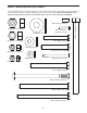
PART IDENTIFICATION CHART M6 x 16mm Screw (51) M14 Nylon Locknut (50) M4 x 25mm Selftapping Screw (54) M14 Washer (68) M12 Nylon Locknut (64) M8 x 60mm Bolt (58) M10 Washer (65) M10 x 65mm Screw (56) M10 Nylon Locknut (67) M6 Washer (70) M6 x 65mm Screw (59) M8 Nylon Locknut (66) M12 x 90mm Bolt (62) M10 x 111mm Bolt Set (63) M10 x 120mm Bolt (57) M10 x 125mm Screw (53) 5 M14 x 180mm Bolt (60) See the drawings below to identify small parts used in assembly.
ASSEMBLY • For help identifying small parts, use the PART IDENTIFICATION CHART on page 5. Make Assembly Easier Everything in this manual is designed to ensure that the weight bench can be assembled successfully by almost anyone. By setting aside plenty of time, assembly will go smoothly. • As you assemble the weight bench, make sure all parts are oriented as shown in the drawings. • Tighten all parts as you assemble them, unless instructed to do otherwise.
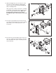
2. Orient the Left Upright (4) as shown. Attach the Left Upright to the Cross Frame (2) with two M10 x 125mm Screws (53) and two M10 Washers (65). 2 5 Attach the Right Upright (5) to the Cross Frame (2) in the same way. 4 2 65 53 3. Orient the Seat Carriage (13) and the Frame (1) as shown, and slide the Seat Carriage onto the Frame.
5. Attach the Frame (1) to the Cross Frame (2) with two M10 x 65mm Screws (56), two M10 Washers (65), two M10 x 120mm Bolts (57), and two M10 Nylon Locknuts (67). 5 67 65 56 See the inset drawing. Attach the Backrest Bumper (36) to the Cross Frame (2) with an M4 x 25mm Self-tapping Screw (54). 65 1 2 57 54 2 6. Attach the Backrest (18) to the Backrest Frame (6) with two M6 x 16mm Screws (51), an M6 x 65mm Screw (59), and an M6 Washer (70). 36 6 18 70 59 6 51 7.
8. Grease an M14 x 180mm Bolt (60). Attach the Pivot Tubes (7) to the Frame (1) with the Bolt, two M14 Washers (68), and an M14 Nylon Locknut (50). Do not overtighten the Nylon Locknut; the Pivot Tubes must pivot easily. 8 18 Grease an M12 x 90mm Bolt (62). Attach the Backrest Frame (6) to the Seat Carriage (13) with the Bolt and an M12 Nylon Locknut (64). Do not overtighten the Nylon Locknut; the Backrest Frame must pivot easily. Grease 68 60 7 6 68 50 64 1 62 Grease 13 9.
11. Slide the Weight Stop (32) onto the post on the Leg Lever (11). Next, tighten the Weight Tube (33) onto the post. Then, attach the Weight Clip (46) to the Weight Tube. 11 63 Next, grease the outside of the barrel of an M10 x 111mm Bolt Set (63). Attach the Leg Lever (11) to the Front Leg (3) with the Bolt Set. Make sure that the barrel of the Bolt Set is inserted through both sides of the bracket on the Front Leg. 3 63 Grease 11 32 33 46 12. Insert the Long Pad Tube (8) into the Front Leg (3).
14. Slide a Safety Spotter (17) onto the Right Upright (5) as shown. Insert the attached Upright Pin (41) into the Safety Spotter and one of the adjustment holes in the Right Upright. Next, slide a Weight Rest (16) onto the Right Upright. Insert the attached Upright Pin (41) into the Weight Rest and one of the adjustment holes in the Right Upright. 14 41 16 5 Attach the other Safety Spotter (17) and the other Weight Rest (16) to the Left Upright (4) in the same way.
ADJUSTMENT This section explains how to adjust the weight bench. See the EXERCISE GUIDELINES on page 15 for important information about how to get the most benefit from your exercise program. Also, see the accompanying exercise guide to see the correct form for several exercises. Properly tighten all parts each time you use the weight bench. Replace any worn parts immediately. To clean the weight bench, use a damp cloth and a mild, non-abrasive detergent; do not use solvents.
ATTACHING THE CURL PAD 20 To use the Curl Pad (20), insert the Curl Post (9) into the Front Leg (3). Secure the Curl Post with the Curl Knob (40). Firmly tighten the Curl Knob. 40 9 3 ATTACHING THE CURL BAR Attach the Curl Frame (10) to the Leg Lever (11) with the Curl Bar Pin (45).
ADJUSTING THE SAFETY SPOTTERS AND THE WEIGHT RESTS 41 Before using your barbell (not included), set the Safety Spotters (17) at the lowest point to which you want your barbell to move. Note: The weight bench is designed to be used only with Olympic weights. 16 5 To adjust each Safety Spotter (17), hold the Safety Spotter and pull out the attached Upright Pin (41).
EXERCISE GUIDELINES THE FOUR BASIC TYPES OF WORKOUTS Muscle Building To increase the size and strength of your muscles, push them close to their maximum capacity. Your muscles will continually adapt and grow as you progressively increase the intensity of your exercise. You can adjust the intensity level of an individual exercise in two ways: • by changing the amount of resistance used • by changing the number of repetitions or sets performed.
COOLING DOWN The repetitions in each set should be performed smoothly and without pausing. The exertion stage of each repetition should last about half as long as the return stage. Proper breathing is important. Exhale during the exertion stage of each repetition and inhale during the return stroke. Never hold your breath. End each workout with 5 to 10 minutes of stretching. Include stretches for both your arms and legs. Move slowly as you stretch and do not bounce.
NOTES 17
PART LIST—Model No. 831.15718.0 Key No. Qty. 1 2 3 4 5 6 7 8 9 10 11 12 13 14 15 16 17 18 19 20 21 22 23 24 25 26 27 28 29 30 31 32 33 34 35 36 37 38 1 1 1 1 1 1 2 1 1 1 1 1 1 1 2 2 2 1 1 1 6 6 2 4 8 1 2 8 2 1 3 1 3 6 1 1 2 4 Description R0807A Key No. Qty.
EXPLODED DRAWING—Model No. 831.15718.
ORDERING REPLACEMENT PARTS To order replacement parts, please see the front cover of this manual. To help us assist you, be prepared to provide the following information when contacting us: • the model number and serial number of the product (see the front cover of the manual) • the name of the product (see the front cover of this manual) • the key number and description of the part(s) (see the PART LIST and the EXPLODED DRAWING near the end of this manual) LIMITED WARRANTY ICON Health & Fitness, Inc.