nordictrack.com Model No. 21917.0 Serial No. Write the serial number in the space above for reference. Serial Number Decal ACTIVATE YOUR WARRANTY To register your product and activate your warranty today, go to my.nordictrack.com. CUSTOMER CARE For service at any time, go to nordictrackservice.com. Or call 1-800-TO-BE-FIT (1-800-862-3348) Mon.–Fri. 6 a.m.–6 p.m. MT Sat. 8 a.m.–12 p.m. MT Please do not contact the store.
TABLE OF CONTENTS WARNING DECAL PLACEMENT . . . . . . . . . . . . . . . . . . . . . . . . . . . . . . . . . . . . . . . . . . . . . . . . . . . . . . . . . . . . . . .2 IMPORTANT PRECAUTIONS. . . . . . . . . . . . . . . . . . . . . . . . . . . . . . . . . . . . . . . . . . . . . . . . . . . . . . . . . . . . . . . . . . 3 BEFORE YOU BEGIN. . . . . . . . . . . . . . . . . . . . . . . . . . . . . . . . . . . . . . . . . . . . . . . . . . . . . . . . . . . . . . . . . . . . . . . .5 PART IDENTIFICATION CHART.
IMPORTANT PRECAUTIONS WARNING: To reduce the risk of serious injury, read all important precautions and instructions in this manual and all warnings on your exercise bike before using your exercise bike. ICON assumes no responsibility for personal injury or property damage sustained by or through the use of this product. 1. It is the responsibility of the owner to ensure that all users of the exercise bike are adequately informed of all precautions. 8.
STANDARD SERVICE PLANS all 4
BEFORE YOU BEGIN Thank you for selecting the revolutionary NORDICTRACK® GX 2.7 U exercise bike. Cycling is an effective exercise for increasing cardiovascular fitness, building endurance, and toning the body. The GX 2.7 U exercise bike provides an impressive selection of features designed to make your workouts at home more effective and enjoyable. reading this manual, please see the front cover of this manual. To help us assist you, note the product model number and serial number before contacting us.
PART IDENTIFICATION CHART Use the drawings below to identify the small parts needed for assembly. The number in parentheses below each drawing is the key number of the part, from the PART LIST near the end of this manual. The number following the key number is the quantity needed for assembly. Note: If a part is not in the hardware kit, check to see if it has been preassembled. Extra parts may be included.
ASSEMBLY • Assembly requires two persons. • In addition to the included tool(s), assembly requires the following tools: • Place all parts in a cleared area and remove the packing materials. Do not dispose of the packing materials until you finish all assembly steps. one Phillips screwdriver one standard screwdriver • Left parts are marked “L” or “Left” and right parts are marked “R” or “Right.” one adjustable wrench Assembly may be easier if you have a set of wrenches.
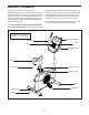
2. Using a standard screwdriver, remove the Shield Cover (26) from the Left and Right Shields (37, 58). 2 26 If there are shipping tubes (not shown) attached to the rear of the Frame (1), remove and discard the shipping screws and the shipping tubes. Next, set a sturdy piece of packing material under the rear of the Frame (50). Have a second person hold the Frame to prevent it from tipping while you complete this step. Identify the Rear Stabilizer (44), which has a handle.
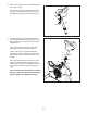
4. Set the Seat Carriage (15) on the Seat Post (18) and hold it in place. 4 Insert the Seat Knob (19) upward into the Seat Post (18), and tighten the Seat Knob into the Seat Bracket (14) inside the Seat Carriage (15). 15 14 18 19 5. Hold the Seat Post (18) near the Frame (50), and position the Seat Post Bushing (21) so that the lock tab (A) is covering the oval hole (B) in the Seat Post. Have a second person loosen the Seat Post Knob (28) a few turns and pull it outward.
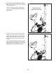
6. Tip: Avoid pinching the Main Wire Harness (25). Orient the Upright (27) as shown, and hold it on the Frame (50). 6 Attach the Upright (27) with four M8 x 20mm Screws (29); start all the Screws, and then tighten them. Avoid pinching the Main Wire Harness (25) 27 29 25 50 7. Locate the lower end of the wire tie (E) in the Upright (27). Tie the wire tie to the Main Wire Harness (25).
8. Orient the Shield Cover (26) as shown, and press it onto the Left and Right Shields (37, 58). 8 26 37, 58 9. Orient the Console Cover (3) as shown, and slide it onto the Upright (27). Tip: Avoid pinching the Main Wire Harness (25). Insert the Pivot Bracket (11) on the Handlebar (4) into the Upright (27). Attach the Pivot Bracket (11) with two M8 x 58mm Bolts (24) and two M8 Locknuts (17). Make sure that the Locknuts are in the hexagonal holes (G).
10. Untie and discard the wire tie on the Main Wire Harness (25). Route the Main Wire Harness upward through the Handlebar (4) as shown. 10 7 While a second person holds the Console (7) near the Handlebar (4), plug the Main Wire Harness (25) and the Pulse Wire Harness (23) into the receptacles on the Console. The connectors on the Main Wire Harness (25) and the Pulse Wire Harness (23) should slide easily into the receptacles and snap into place.
. Identify the Right Pedal (60). Using an adjustable wrench, firmly tighten the Right Pedal (60) clockwise into the Right Crank Arm (59). Firmly tighten the Left Pedal (32) counterclockwise into the Left Crank Arm (not shown). IMPORTANT: You must turn the Left Pedal counterclockwise to attach it. Adjust the strap on the Right Pedal (60) to the desired position, and press the ends of the strap (H) onto the tabs (I) on the Right Pedal.
HOW TO USE THE EXERCISE BIKE HOW TO PLUG IN THE POWER ADAPTER HOW TO ADJUST THE HEIGHT OF THE SEAT IMPORTANT: If the exercise bike has been exposed to cold temperatures, allow it to warm to room temperature before you plug in the power adapter. If you do not do this, you may damage the console displays or other electronic components. For effective exercise, the seat should be at the proper height. As you pedal, there should be a slight bend in your knees when the pedals are in the lowest position.
HOW TO ADJUST THE ANGLE OF THE HANDLEBAR HOW TO ADJUST THE PEDAL STRAPS To adjust the pedal straps, first pull the ends of the straps (F) off the tabs (G) on the pedals. Then, adjust the straps to the desired position, and press the ends of the straps onto the tabs. To adjust the angle of the handlebar, loosen the handlebar knob (E), rotate the handlebar to the desired angle, and then tighten the handlebar knob.
CONSOLE DIAGRAM FEATURES OF THE CONSOLE The advanced console offers an array of features designed to make your workouts more effective and enjoyable. When you use the manual mode of the console, you can change the resistance of the pedals with the touch of a button. As you exercise, the console will provide continuous exercise feedback. You can even measure your heart rate using the handgrip heart rate monitor or a compatible heart rate monitor.
HOW TO USE THE MANUAL MODE 4. Follow your progress with the displays. 1. Begin pedaling or press any button on the console to turn on the console. The display can show the following workout information: When you turn on the console, the display will turn on. The console will then be ready for use. Calories (CALS)—When the manual mode and most onboard workouts are selected, the approximate number of calories you have burned.
Press the Next Display button repeatedly to view the desired workout information in the display. To change the volume level of the console, press the volume increase and decrease buttons. To pause the console, simply stop pedaling. When the console is paused, the time will flash in the display. To continue your workout, simply resume pedaling. Scan mode—The console also has a scan mode that will display workout information in a repeating cycle.
When your pulse is detected, your heart rate will be shown in the display. For the most accurate heart rate reading, hold the contacts for at least 15 seconds. HOW TO USE AN ONBOARD WORKOUT If the display does not show your heart rate, make sure that your hands are positioned as described. Be careful not to move your hands excessively or to squeeze the contacts tightly. For optimal performance, clean the contacts using a soft cloth; never use alcohol, abrasives, or chemicals to clean the contacts.
IMPORTANT: The target speed is intended only to provide motivation. Your actual pedaling speed may be slower than the target speed. Make sure to pedal at a speed that is comfortable for you. HOW TO USE THE SOUND SYSTEM To play music or audio books through the console sound system while you exercise, plug a 3.5 mm male to 3.5 mm male audio cable (not included) into the jack on the console and into a jack on your personal audio player; make sure that the audio cable is fully plugged in.
HOW TO CONNECT YOUR TABLET TO THE CONSOLE 5. Disconnect your tablet from the console if desired. The console supports BLUETOOTH connections to tablets via the iFit Bluetooth Tablet app and to compatible heart rate monitors. Note: Other BLUETOOTH connections are not supported. To disconnect your tablet from the console, first select the disconnect option in the iFit Bluetooth Tablet app. Then, press and hold the iFit Sync button on the console until the LED on the console turns solid green. 1.
HOW TO CHANGE CONSOLE SETTINGS 1. Select the settings mode. To select the settings mode, press the Settings button. The first settings screen will appear in the display. otal Distance—The letters MI or KM will appear T in the display. The display will show the total distance (in miles or kilometers) that the exercise bike has been pedaled. 2. Navigate the settings mode. While the settings mode is selected, you can navigate through several settings screens.
MAINTENANCE AND TROUBLESHOOTING MAINTENANCE Locate the Reed Switch (64). Slightly loosen the M4 x 19mm Screw (65). Regular maintenance is important for optimal performance and to reduce wear. Inspect and properly tighten all parts each time the exercise bike is used. Replace any worn parts immediately. To clean the exercise bike, use a damp cloth and a small amount of mild soap. IMPORTANT: To avoid damage to the console, keep liquids away from the console and keep the console out of direct sunlight.
HOW TO ADJUST THE DRIVE BELT Using an M10 socket wrench with an extension (not included), reach into the opening in the bottom of the Right Shield (58) and tighten the M10 x 50mm Screw (49) a few turns until the Drive Belt (not shown) is tight; do not overtighten the Drive Belt. If you can feel the pedals slip while you are pedaling, even when the resistance is adjusted to the highest level, the drive belt may need to be adjusted. To adjust the drive belt, first unplug the power adapter.
EXERCISE GUIDELINES Burning Fat—To burn fat effectively, you must exercise at a low intensity level for a sustained period of time. During the first few minutes of exercise, your body uses carbohydrate calories for energy. Only after the first few minutes of exercise does your body begin to use stored fat calories for energy. If your goal is to burn fat, adjust the intensity of your exercise until your heart rate is near the lowest number in your training zone.
PART LIST Model No. 21917.0 R0817A Key No. Qty. Description Key No. Qty.
EXPLODED DRAWING 36 Model No. 21917.
ORDERING REPLACEMENT PARTS To order replacement parts, please see the front cover of this manual.