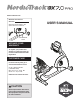
www.nordictrack.com Model No. 831.21977.2 Serial No. Write the serial number in the space above for reference. Serial Number Decal ACTIVATE YOUR WARRANTY To register your product and activate your warranty today, go to www.nordictrackservice.com/ registration. CUSTOMER CARE For service at any time, go to www.nordictrackservice.com. Or call 1-800-TO-BE-FIT (1-800-862-3348) Mon.–Fri. 6 a.m.–6 p.m. MT Sat. 8 a.m.–12 p.m. MT Please do not contact the store.
TABLE OF CONTENTS WARNING DECAL PLACEMENT . . . . . . . . . . . . . . . . . . . . . . . . . . . . . . . . . . . . . . . . . . . . . . . . . . . . . . . . . . . . . . . 2 IMPORTANT PRECAUTIONS . . . . . . . . . . . . . . . . . . . . . . . . . . . . . . . . . . . . . . . . . . . . . . . . . . . . . . . . . . . . . . . . . . 3 BEFORE YOU BEGIN. . . . . . . . . . . . . . . . . . . . . . . . . . . . . . . . . . . . . . . . . . . . . . . . . . . . . . . . . . . . . . . . . . . . . . . .
IMPORTANT PRECAUTIONS WARNING: To reduce the risk of serious injury, read all important precautions and instructions in this manual and all warnings on your exercise bike before using your exercise bike. ICON assumes no responsibility for personal injury or property damage sustained by or through the use of this product. 1. It is the responsibility of the owner to ensure that all users of the exercise bike are adequately informed of all precautions. 8.
STANDARD SERVICE PLANS all 5
BEFORE YOU BEGIN Thank you for selecting the revolutionary NORDICTRACK® GX 7.0 PRO exercise bike. Cycling is an effective exercise for increasing cardiovascular tness, building endurance, and toning the body. The GX 7.0 PRO exercise bike provides an impressive selection of features designed to make your workouts at home more effective and enjoyable. reading this manual, please see the front cover of this manual. To help us assist you, note the product model number and serial number before contacting us.
PART IDENTIFICATION CHART Use the drawings below to identify the small parts needed for assembly. The number in parentheses below each drawing is the key number of the part, from the PART LIST near the end of this manual. The number following the key number is the quantity needed for assembly. Note: If a part is not in the hardware kit, check to see if it has been preassembled. Extra parts may be included.
ASSEMBLY • To watch an assembly video, go to http://productvideo.co/ assembly/sears/nordictrack or use your mobile phone or smartphone to read the QR code at the right. • Left parts are marked “L” or “Left” and right parts are marked “R” or “Right.” • To identify small parts, see page 7. In addition to the included tool(s), assembly requires the following tools: one Phillips screwdriver • Assembly requires two persons.
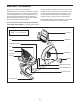
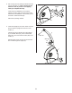
3. Set a sturdy piece of packing material under the front of the Frame (1). Have a second person hold the Frame to prevent it from tipping while you complete this step. 3 Wheel Orient the Front Stabilizer (15) so that the wheels are facing away from the exercise bike. Attach the Front Stabilizer to the Frame (1) with two M10 x 122mm Screws (65). 15 Remove the packing material. 1 4. Orient the Upright (2) as shown. Have a second person hold the Upright near the front of the Frame (1).
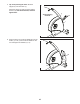
5. Tip: Avoid pinching the wires. Slide the Upright (2) onto the Frame (1). 5 Attach the Upright (2) with four M10 x 62mm Screws (70); start all the Screws, and then tighten them. Avoid pinching the wires 2 70 1 6. Press the mount on the Front Shield (58) into the Frame (1). Then, press the Front Shield into the Left and Right Front Shields (13, 14).
7. Orient the Upright Cover (57) as shown. Hold the Upright Cover near the Upright (2), and insert the wires upward through the Upright Cover. 7 2 Then, slide the Upright Cover (57) onto the Upright (2). Wire Tie 57 Wires 8. Orient the Handlebar (7) as shown. While a second person holds the Handlebar near the Upright (2), insert the wires upward through the Handlebar. 8 7 Tip: Avoid pinching the wires. Attach the Handlebar (7) to the Upright (2) with two M8 x 22mm Screws (69).
10. Tip: Avoid pinching the wires. Attach the Console (4) to the Handlebar (7) with four M4 x 16mm Screws (77). 10 4 7 77 Avoid pinching the wires 11. Attach the Upright Cover (57) to the Handlebar (7) with two M4 x 16mm Screws (77). 11 7 57 77 12. Attach the Seat Handlebar (10) to the Seat Carriage (41) with four M8 x 38mm Screws (67); start all the Screws, and then tighten them.
. Slide the Accessory Tray (56) onto the Seat Handlebar (10). 13 56 Attach the Accessory Tray (56) to the Seat Handlebar (10) with four M4 x 16mm Screws (77). 10 77 77 14. Orient the Seat (9) as indicated by the sticker. 14 9 Attach the Seat (9) to the Seat Handlebar (10) with four M6 x 18mm Screws (25) and four M6 Washers (88) (only two of each are shown); start all the Screws, and then tighten them.
15. Slide the Backrest Back (81) onto the Seat Handlebar (10). 15 Attach the Backrest Back (81) with four M6 x 30mm Screws (75) and four M6 Washers (88); start all the Screws, and then tighten them. 81 88 75 10 16. Identify the Right Pedal (21). 16 Using an adjustable wrench, firmly tighten the Right Pedal (21) clockwise into the Right Crank Arm (23). 23 Firmly tighten the Left Pedal (not shown) counterclockwise into the Left Crank Arm (not shown).
17. Plug the Power Adapter (51) into the receptacle on the frame of the exercise bike. 17 Note: To plug the Power Adapter (51) into an outlet, see HOW TO PLUG IN THE POWER ADAPTER on page 17. 51 18. After the exercise bike is assembled, inspect it to make sure that it is assembled correctly and that it functions properly. Make sure that all parts are properly tightened before you use the exercise bike. Note: Extra parts may be included. Place a mat beneath the exercise bike to protect the floor.
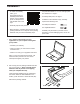
THE CHEST HEART RATE MONITOR HOW TO PUT ON THE HEART RATE MONITOR The heart rate monitor consists of a chest strap and a sensor. Insert the tab on one end of the chest strap into the hole in one end of the sensor as shown. Then, press the end of the sensor under the buckle on the chest strap. The tab should be flush with the front of the sensor.
HOW TO USE THE EXERCISE BIKE HOW TO PLUG IN THE POWER ADAPTER HOW TO ADJUST THE PEDAL STRAPS IMPORTANT: If the exercise bike has been exposed to cold temperatures, allow it to warm to room temperature before plugging in the power adapter. If you do not do this, you may damage the console displays or other electronic components. To adjust the pedal straps, rst pull the ends of the straps off the tabs on the pedals.
CONSOLE DIAGRAM FEATURES OF THE CONSOLE The console also features an iFit mode that enables the console to communicate with your wireless network through an optional iFit module. With the iFit mode, you can download personalized workouts, create your own workouts, track your workout results, race against other iFit users, and access many other features. To purchase an iFit module at any time, go to www.iFit.com or call the telephone number on the front cover of this manual.
HOW TO USE THE MANUAL MODE Calories per Hour (Calories/Hr)—This display mode will show the approximate number of calories you are burning per hour. 1. Begin pedaling or press any button on the console to turn on the console. Distance (Dist.)—This display mode will show the distance that you have pedaled in miles or kilometers. When you turn on the console, the display will turn on. The console will then be ready for use. 2. Select the manual mode.
Press the Home button to exit the workout and return to the default menu (see HOW TO CHANGE CONSOLE SETTINGS on page 24 to set the default menu). If necessary, press the Home button again. to squeeze the contacts tightly. For optimal performance, clean the contacts using a soft cloth; never use alcohol, abrasives, or chemicals to clean the contacts. 6. Turn on the fan if desired.
HOW TO USE AN ONBOARD WORKOUT resistance level and/or target speed is programmed for the next segment, the resistance level and/or target speed will appear in the display for a few seconds to alert you. The resistance of the pedals will then change. 1. Begin pedaling or press any button on the console to turn on the console. When you turn on the console, the display will turn on. The console will then be ready for use.
HOW TO USE A SET-A-GOAL WORKOUT Note: The calorie goal is an estimate of the number of calories that you will burn during the workout. The actual number of calories that you burn will depend on various factors such as your weight. In addition, if you manually change the resistance during the workout, the number of calories you burn will be affected. 1. Begin pedaling or press any button on the console to turn on the console. When you turn on the console, the display will turn on.
HOW TO USE AN IFIT WORKOUT For more information on the iFit workouts, please see www.iFit.com. You must have an iFit module to use an iFit workout. To purchase an iFit module at any time, go to www.iFit.com or call the telephone number on the front cover of this manual. When you select an iFit workout, the display will show the duration of the workout and the approximate number of calories you will burn. The display may also show the name of the workout.
HOW TO CHANGE CONSOLE SETTINGS Units—The currently selected unit of measurement will appear in the display. To change the unit of measurement, press the Enter button repeatedly. To view distance in miles, select ENGLISH. To view distance in kilometers, select METRIC. 1. Select the settings mode. To select the settings mode, press and hold down the Display button for a few seconds until the settings mode appears in the display.
MAINTENANCE AND TROUBLESHOOTING Inspect and tighten all parts of the exercise bike regularly. Replace any worn parts immediately. Next, remove the M4 x 16mm Screw (77) from the Access Cover (40). Then, remove the Access Cover. To clean the exercise bike, use a damp cloth and a small amount of mild soap. IMPORTANT: To avoid damage to the console, keep liquids away from the console and keep the console out of direct sunlight. Locate the Reed Switch (46).
HOW TO ADJUST THE DRIVE BELT Next, loosen the M6 x 20mm Hex Screw (84). Tighten the M10 x 50mm Hex Screw (83) until the Drive Belt (47) is tight. When the Drive Belt is tight, tighten the M6 x 20mm Hex Screw. If the pedals slip while you are pedaling, even while the resistance is adjusted to the highest setting, the drive belt may need to be adjusted. To adjust the drive belt, first unplug the power adapter (not shown). 47 See EXPLODED DRAWING B on page 31.
EXERCISE GUIDELINES Burning Fat—To burn fat effectively, you must exercise at a low intensity level for a sustained period of time. During the first few minutes of exercise, your body uses carbohydrate calories for energy. Only after the first few minutes of exercise does your body begin to use stored fat calories for energy. If your goal is to burn fat, adjust the intensity of your exercise until your heart rate is near the lowest number in your training zone.
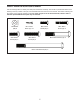
PART LIST Key No. Qty. 1 2 3 4 5 6 7 8 9 10 11 12 13 14 15 16 17 18 19 20 21 22 23 24 25 26 27 28 29 30 31 32 33 34 35 36 37 38 39 40 41 42 43 44 45 1 1 2 1 1 1 1 1 1 1 1 1 1 1 1 1 2 1 2 1 1 1 1 1 4 1 1 2 1 2 1 1 2 1 2 1 1 11 1 1 1 1 1 1 1 Model No. 831.21977.2 R1113A Description Key No. Qty.
Key No. Qty. 91 92 93 94 95 96 97 98 8 2 2 7 2 2 1 1 Description Key No. Qty. M8 Split Washer Crank Cap M6 Locknut Tree Fastener M10 Flange Nut M6 Split Washer Right Rear Shield Left Rear Shield 99 100 101 102 103 * * 4 1 1 2 1 – – Description M6 Small Washer Clip Nut Power Receptacle/Wire #6 x 12mm Screw M8 x 28mm Hex Screw Assembly Tool User’s Manual Note: Specifications are subject to change without notice. For information about ordering replacement parts, see the back cover of this manual.
77 75 88 30 77 38 77 77 94 88 75 102 56 77 75 77 81 94 77 88 38 98 25 25 9 77 94 8 97 88 52 77 77 4 77 77 77 69 69 53 13 7 77 49 44 20 14 54 38 100 77 77 38 77 57 77 77 40 77 85 72 38 77 2 52 58 70 EXPLODED DRAWING A Model No. 831.21977.
90 99 89 55 55 38 89 64 63 59 74 91 18 89 63 59 27 64 55 91 89 41 32 12 77 10 67 96 74 48 65 19 74 74 91 16 26 60 59 93 55 64 91 73 99 55 59 99 62 89 6 77 11 67 19 80 71 62 93 62 22 48 80 5 92 24 76 82 60 43 42 39 37 71 36 28 62 103 38 50 46 1 86 79 33 95 34 28 89 45 77 51 33 35 89 95 30 31 61 68 84 83 85 3 48 66 35 30 101 15 47 87 78 50 29 3 78 17 92 85 23 21 48 66 17 65 EXPLODED DRAWING B Mo
ORDERING REPLACEMENT PARTS To order replacement parts, please see the front cover of this manual.