www.nordictrack.com Model No. 831.23897.1 Serial No. Write the serial number in the space above for reference. Serial Number Decal (under frame) ACTIVATE YOUR WARRANTY To register your product and activate your warranty today, go to www.nordictrackservice.com/ registration. CUSTOMER CARE For service at any time, go to www.nordictrackservice.com. Or call 1-800-TO-BE-FIT (1-800-862-3348) Mon.–Fri. 6 a.m.–6 p.m. MT Sat. 8 a.m.–4 p.m. MT Please do not contact the store.
TABLE OF CONTENTS WARNING DECAL PLACEMENT . . . . . . . . . . . . . . . . . . . . . . . . . . . . . . . . . . . . . . . . . . . . . . . . . . . . . . . . . . . . . . . 2 IMPORTANT PRECAUTIONS . . . . . . . . . . . . . . . . . . . . . . . . . . . . . . . . . . . . . . . . . . . . . . . . . . . . . . . . . . . . . . . . . . 3 BEFORE YOU BEGIN. . . . . . . . . . . . . . . . . . . . . . . . . . . . . . . . . . . . . . . . . . . . . . . . . . . . . . . . . . . . . . . . . . . . . . . .
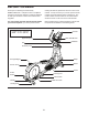
IMPORTANT PRECAUTIONS WARNING: To reduce the risk of burns, fire, electric shock, or injury to persons, read all important precautions and instructions in this manual and all warnings on your elliptical before using your elliptical. ICON assumes no responsibility for personal injury or property damage sustained by or through the use of this product. 1. It is the responsibility of the owner to ensure that all users of the elliptical are adequately informed of all precautions. 11.
STANDARD SERVICE PLANS all 5
BEFORE YOU BEGIN Thank you for selecting the revolutionary NORDICTRACK® E 7.5 elliptical. The E 7.5 elliptical provides an impressive selection of features designed to make your workouts at home more effective and enjoyable. reading this manual, please see the front cover of this manual. To help us assist you, note the product model number and serial number before contacting us. The model number and the location of the serial number decal are shown on the front cover of this manual.
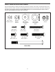
PART IDENTIFICATION CHART Use the drawings below to identify the small parts needed for assembly. The number in parentheses below each drawing is the key number of the part, from the PART LIST near the end of this manual. The number following the key number is the quantity needed for assembly. Note: If a part is not in the hardware kit, check to see if it has been preassembled. Extra parts may be included.
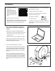
ASSEMBLY • To watch an assembly video, go to http://productvideo.co/ assembly/sears/nordictrack or use your mobile phone or smartphone to read the QR code at the right. • Left parts are marked “L” or “Left” and right parts are marked “R” or “Right.” • To identify small parts, see page 7. • In addition to the included tool(s), assembly requires the following tools: one Phillips screwdriver • Assembly requires two persons.
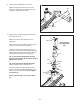
3. Orient the Front Stabilizer (3) as shown. 3 While a second person lifts the front of the Frame (1), attach the Front Stabilizer (3) with two M10 x 120mm Screws (100). 3 100 1 4. Identify and orient the Upright (5) and the Top Cover (23) as shown. 4 Slide the Top Cover (23) upward onto the Upright (5). Wire Tie Avoid pinching the Upright Wire (60) Have a second person hold the Upright (5) and the Top Cover (23) near the Frame (1). Locate the wire tie in the Upright (5).
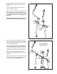
5. Identify the Right Upper Body Arm (8) and the Right Upper Body Leg (6) and orient them as shown. 5 Insert the Right Upper Body Arm (8) into the Right Upper Body Leg (6). Attach the Right Upper Body Arm (8) with three M8 x 45mm Bolts (104) and three M8 Locknuts (105). Make sure that the Locknuts are inside the hexagonal holes. Do not fully tighten the Bolts yet. 9 Assemble the Left Upper Body Arm (9) and the Left Upper Body Leg (7) in the same way. 8 104 104 105 105 104 Hexagonal Holes 6 7 6.
7. Note: The Leveling Foot (41) may be preattached. 7 With the help of a second person, place some of the packaging materials (not shown) under the Frame (1). Have the second person hold the Frame to prevent it from tipping while you complete this step. 1 Tighten the Leveling Foot (41) into the underside of the Frame (1). 41 8. Identify the Right Pedal (14) and the Right Pedal Arm (12) and orient them as shown.
9. See the upper drawing. Locate the Ramp Roller (92) on the Right Pedal Arm (12). 9 Set the Ramp Roller (92) on the right side of the Ramp (43). 12 92 See the lower drawing. Pull upward on the Latch (117) on the Right Pedal Arm (12). Press the Right Pedal Arm (12) onto the right Sleeve (136). Make sure that the Right Pedal Arm latches into place. Repeat this step on the other side of the elliptical. 43 12 117 136 10. Orient the Ramp Cover (44) around the Upright (5) as shown.
11. Apply grease to a Link Arm Axle (94) and to an M17 x 27mm Wave Washer (88). 11 First, insert the Link Arm Axle (94) into the Right Upper Body Leg (6) from the side shown. Next, slide the M17 x 27mm Wave Washer (88) onto the Link Arm Axle. Then, insert the Link Arm Axle into the Right Link Arm (90). 7 91 Insert a hex key into the M8 x 25mm Screw (128) in the Link Arm Axle (94). 128 94 6 Using a second hex key, tighten another M8 x 25mm Screw (128), a Pivot Axle Cover (111), and an M8 x 25mm x 1.
13. Orient the Rear Upright Cover (24) as shown. 13 While a second person holds the Rear Upright Cover (24) near the Upright (5), connect the receiver wire (A) to the Receiver Extension Wire (143). Avoid pinching the wires 5 Tip: Avoid pinching the wires. Attach the Rear Upright Cover (24) to the Upright (5) with four M4 x 16mm Screws (93). Tip: It may be necessary to bend the upper end of the Rear Upright Cover gently into place around the Upright. 24 93 A 143 14.
16. Identify the Right Rear Leg Cover (29). 16 Attach the Right Rear Leg Cover (29) around the Right Upper Body Arm (8) by pressing it into the Right Front Leg Cover (30). 8 Repeat this step on the other side of the elliptical. 30 29 17. Orient the Console Cover (11) as shown. Slide the Console Cover onto the Upright (5).
18. Have a second person hold the Handlebar (10) near the Upright (5). 18 10 135 See the inset drawing. Locate the Pulse Wire (135) in the Handlebar (10). Insert the Pulse Wire into the front of the Upright (5) and pull it out of the hole in the Upright as shown. 5 Tie the end of the wire tie to the Upright Wire (60), the Receiver Extension Wire (143), and the Pulse Wire (135). Then, insert the other end of the wire tie upward through the Handlebar (10).
20. While a second person holds the Console (33) near the Handlebar (10), connect the wires on the Console to the Upright Wire (60), to the Receiver Extension Wire (143), and to the Pulse Wire (135). 20 33 Avoid pinching the wires Insert the excess wire into the Handlebar (10) or into the Console (33). 143 135 Tip: Avoid pinching the wires. Attach the Console (33) to the Handlebar (10) with four M4 x 16mm Screws (93). 10 60 93 21.
HOW TO USE THE ELLIPTICAL HOW TO PLUG IN THE POWER CORD A temporary adapter may be used to connect the power cord to a 2-pole receptacle as shown at the right if a properly grounded outlet is not available. This product must be grounded. If it should malfunction or break down, grounding provides a path of least resistance for electric current to reduce the risk of electric shock. The power cord has a plug with a grounding pin.
HOW TO FOLD AND UNFOLD THE ELLIPTICAL HOW TO MOVE THE ELLIPTICAL When the elliptical is not in use, the frame can be folded out of the way. First, lift the latch under each pedal arm, and lift the pedal arms off the sleeves on the crank arms. To move the elliptical, first fold it as described at the left. Next, stand in front of the elliptical, hold the upright, and place one foot against one of the wheels. Pull the upright until the elliptical rolls on the wheels.
HOW TO EXERCISE ON THE ELLIPTICAL To dismount the elliptical, wait until the pedals come to a complete stop. Note: The elliptical does not have a free wheel; the pedals will continue to move until the flywheel stops. When the pedals are stationary, step off the higher pedal first. Then, step off the lower pedal. To mount the elliptical, hold the upper body arms and step onto the pedal that is in the lowest position. Next, step onto the other pedal.
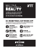
CONSOLE DIAGRAM MAKE YOUR FITNESS GOALS A REALITY WITH IFIT.COM Choose and download sets of weight-loss workouts. With your new iFit-compatible fitness equipment, you can use an array of features on iFit.com to make your fitness goals a reality: Go to iFit.com to learn more. Run anywhere in the world with customizable Google Maps. FEATURES OF THE CONSOLE Download training workouts designed to help you reach your personal goals.
The console also features an iFit mode that enables the console to communicate with your wireless network through an optional iFit module. With the iFit mode, you can download personalized workouts, create your own workouts, track your workout results, race against other iFit users, and access many other features. To purchase an iFit module at any time, go to www.iFit.com or call the telephone number on the front cover of this manual.
HOW TO USE THE MANUAL MODE Calories (Cals.)—This display mode will show the approximate number of calories you have burned. 1. Begin pedaling or press any button on the console to turn on the console. Calories per Hour (Cals./Hr)—This display mode will show the approximate number of calories you are burning per hour. See HOW TO TURN ON THE POWER above. 2. Select the manual mode. Distance (Dist.)—This display mode will show the distance that you have pedaled in miles or kilometers.
As you exercise, the workout intensity level bar will indicate the approximate intensity level of your exercise. rate, hold the handgrip heart rate monitor with your palms resting against the contacts. Avoid moving your hands or gripping the contacts tightly. When your pulse is detected, a heart symbol will flash in the display each time your heart beats, one or two dashes will appear, and then your heart rate will be shown.
HOW TO USE AN ONBOARD WORKOUT resistance level, ramp incline level, and/or target rpm is programmed for the next segment, the resistance level, ramp incline level, and/or target rpm will appear in the display for a few seconds to alert you. The resistance of the pedals and the incline level of the ramp will then change. 1. Begin pedaling or press any button on the console to turn on the console. See HOW TO TURN ON THE POWER on page 22.
HOW TO USE A SET-A-GOAL WORKOUT Note: The calorie goal is an estimate of the number of calories that you will burn during the workout. The actual number of calories that you burn will depend on various factors such as your weight. In addition, if you manually change the resistance or incline of the ramp during the workout, the number of calories you burn will be affected. 1. Begin pedaling or press any button on the console to turn on the console. See HOW TO TURN ON THE POWER on page 22. 2.
HOW TO USE AN IFIT WORKOUT To compete in a race that you have previously scheduled, press the Compete button. You must have an iFit module to use an iFit workout. To re-run a recent iFit workout from your schedule, first press the Track button. Next, press the increase and decrease buttons to select the desired workout. Then, press the Enter button to start the workout. To purchase an iFit module at any time, go to www.iFit.com or call the telephone number on the front cover of this manual.
6. Follow your progress with the display. HOW TO USE THE SOUND SYSTEM See step 4 on page 25. The My Trail tab will show a map of the trail you are walking or running or it will show a track and the number of laps you complete. To play music or audio books through the console sound system while you exercise, plug your audio cable into the jack on the console and into a jack on your MP3 player or CD player; make sure that your audio cable is fully plugged in.
HOW TO CHANGE CONSOLE SETTINGS If no module is connected, the display will show the words NO IFIT MODULE. If no module is connected, go to step 10. The console features a user mode that allows you to view usage information, select a unit of measurement, and adjust the contrast level of the display. 6. Select an audio setting for the voice of the personal trainer if desired.
FCC INFORMATION This equipment has been tested and found to comply with the limits for a Class B digital device, pursuant to part 15 of the FCC Rules. These limits are designed to provide reasonable protection against harmful interference in a residential installation. This equipment generates, uses, and can radiate radio frequency energy and, if not installed and used in accordance with the instructions, may cause harmful interference to radio communications.
MAINTENANCE AND TROUBLESHOOTING Inspect and tighten all parts of the elliptical regularly. Replace any worn parts immediately. HOW TO ADJUST THE REED SWITCH If the console does not display correct feedback, the reed switch should be adjusted. To clean the elliptical, use a damp cloth and a small amount of mild soap. IMPORTANT: To avoid damage to the console, keep liquids away from the console and keep the console out of direct sunlight. To adjust the reed switch, first unplug the power cord.
HOW TO ADJUST THE DRIVE BELT See EXPLODED DRAWING B on page 37. Remove the M4 x 16mm Screws (93) and the M4 x 42mm Screws (124) from the Right and Left Shields (18, 19). Make sure to note which size Screws come from which holes. Then, carefully remove the Left Shield. If you can feel the pedals slip while you are pedaling, even when the resistance is adjusted to the highest level, the drive belt may need to be adjusted. To adjust the drive belt, first unplug the power cord.
EXERCISE GUIDELINES Burning Fat—To burn fat effectively, you must exercise at a low intensity level for a sustained period of time. During the first few minutes of exercise, your body uses carbohydrate calories for energy. Only after the first few minutes of exercise does your body begin to use stored fat calories for energy. If your goal is to burn fat, adjust the intensity of your exercise until your heart rate is near the lowest number in your training zone.
PART LIST Key No. Qty. 1 2 3 4 5 6 7 8 9 10 11 12 13 14 15 16 17 18 19 20 21 22 23 24 25 26 27 28 29 30 31 32 33 34 35 36 37 38 39 40 41 42 43 44 45 46 47 48 49 50 1 1 1 1 1 1 1 1 1 1 1 1 1 1 1 2 2 1 1 1 1 1 1 1 1 1 1 1 1 1 1 1 1 2 2 2 4 1 2 8 3 1 1 1 1 4 1 1 1 1 Model No. 831.23897.1 R1112C Description Key No. Qty.
Key No. Qty. 101 102 103 104 105 106 107 108 109 110 111 112 113 114 115 116 117 118 119 120 121 122 123 124 125 126 127 1 20 2 6 6 12 4 4 1 2 6 2 2 2 2 4 2 2 2 14 2 1 2 4 1 8 2 Description Key No. Qty. Anchored Zip Tie M8 x 16mm Screw M10 Locknut M8 x 45mm Bolt M8 Locknut Link Arm Bushing M10 x 25mm Screw M10 Washer Frame Wire M8 x 23.
31 126 102 57 105 104 93 9 93 93 35 7 33 88 104 105 57 32 102 24 10 93 26 34 93 93 102 93 34 131 131 57 11 93 143 23 93 102 48 57 131 102 131 5 93 135 88 29 25 57 105 93 6 35 8 102 104 57 126 30 93 EXPLODED DRAWING A Model No. 831.23897.
40 40 142 37 37 100 41 93 38 39 60 72 16 4 75 41 125 109 73 75 37 89 95 93 133 101 78 19 59 93 68 93 77 89 85 69 70 138 124 93 2 96 76 97 87 86 93 86 99 74 120 17 27 124 28 76 93 87 89 122 71 61 18 20 93 120 120 40 142 17 39 16 124 124 EXPLODED DRAWING B Model No. 831.23897.
108 107 45 46 120 44 38 107 120 64 42 110 67 66 102 108 46 120 41 64 63 64 53 65 110 102 120 120 43 108 107 64 47 83 83 84 82 119 93 93 55 81 49 79 52 22 51 1 93 108 107 81 102 102 84 54 80 37 52 80 21 93 141 56 93 50 58 119 79 3 36 82 56 55 93 103 37 100 93 93 58 36 141 EXPLODED DRAWING C Model No. 831.23897.
138 132 117 121 138 114 112 127 123 91 62 140 134 126 106 116 118 129 111 128 137 136 113 102 13 115 145 106 138 138 132 117 121 123 139 62 88 106 140 15 134 12 118 137 116 114 139 136 128 126 111 94 130 138 92 98 106 112 140 139 113 62 89 129 144 127 89 62 140 94 98 106 106 126 115 106 92 111 126 130 128 14 102 111 90 88 106 126 106 128 111 EXPLODED DRAWING D Model No. 831.23897.
ORDERING REPLACEMENT PARTS To order replacement parts, please see the front cover of this manual.