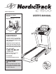
www.nordictrack.com Model No. 831.24992.2 Serial No. Write the serial number in the space above for reference. Serial Number Decal QUESTIONS? If you have questions, or if parts are damaged or missing, DO NOT CONTACT THE STORE; please contact Customer Care. IMPORTANT: Please register this product (see the limited warranty on the back cover of this manual) before contacting Customer Care. 1-800-TO-BE-FIT CALL TOLL-FREE: (1-800-862-3348) Mon.–Fri. 6 a.m.–6 p.m. MT Sat. 8 a.m.–4 p.m. MT ON THE WEB: www.
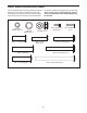
TABLE OF CONTENTS WARNING DECAL PLACEMENT . . . . . . . . . . . . . . . . . . . . . . . . . . . . . . . . . . . . . . . . . . . . . . . . . . . . . . . . . . . . . .2 IMPORTANT PRECAUTIONS . . . . . . . . . . . . . . . . . . . . . . . . . . . . . . . . . . . . . . . . . . . . . . . . . . . . . . . . . . . . . . . .3 BEFORE YOU BEGIN . . . . . . . . . . . . . . . . . . . . . . . . . . . . . . . . . . . . . . . . . . . . . . . . . . . . . . . . . . . . . . . . . . . . . .5 PART IDENTIFICATION CHART . . . . .
IMPORTANT PRECAUTIONS WARNING: To reduce the risk of serious injury, read all important precautions and instructions in this manual and all warnings on your treadmill before using your treadmill. ICON assumes no responsibility for personal injury or property damage sustained by or through the use of this product. 1. Before beginning any exercise program, consult your physician. This is especially important for persons over age 35 or persons with pre-existing health problems. carrying 15 or more amps.
24. Inspect and properly tighten all parts of the treadmill regularly. 20. Never leave the treadmill unattended while it is running. Always remove the key, unplug the power cord, and press the power switch into the off position when the treadmill is not in use. (See the drawing on page 5 for the location of the power switch.) 25. 21. Do not attempt to raise, lower, or move the treadmill until it is properly assembled. (See ASSEMBLY on page 7, and HOW TO FOLD AND MOVE THE TREADMILL on page 24.
BEFORE YOU BEGIN Thank you for selecting the revolutionary NORDICTRACK® C 1500 treadmill. The C 1500 treadmill offers an impressive selection of features designed to make your workouts at home more enjoyable and effective. And when youʼre not exercising, the unique treadmill can be folded up, requiring less than half the floor space of other treadmills. ing this manual, please see the front cover of this manual.
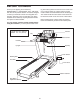
PART IDENTIFICATION CHART Use the drawings below to identify small parts used for assembly. The number in parentheses below each drawing is the key number of the part, from the PART LIST near the end of this manual. The number follow- 5/16" Star Washer (10)–10 3/8" Star Washer (12)–4 3/8" x 1 1/4" Screw (8)–4 ing the key number is the quantity used for assembly. Note: If a part is not in the hardware kit, check to see if it is preattached. Some extra hardware may be included.
ASSEMBLY • Assembly requires two persons. • To identify small parts, see page 6. • Place all parts in a cleared area and remove the packing materials. Do not dispose of the packing materials until you finish assembly. • Assembly requires the following tools: the included hex key • The underside of the walking belt is coated with high-performance lubricant. After shipping, there may be some lubricant on top of the walking belt or on the shipping carton. This is normal.
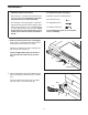
3. Identify the Left Upright (89), which is marked with a “Left” sticker. Have a second person hold the Left Upright near the Base (97). 3 84 See the inset drawing. Tie the wire tie in the Left Upright (89) securely around the end of the Upright Wire (84). Then, pull the other end of the wire tie until the Upright Wire is routed completely through the Left Upright. 89 Wire Tie Wire Tie 89 84 4. Hold the Left Upright (89) against the Base (97). Be careful not to pinch the wires.
5. Identify the Left and Right Base Covers (92, 93). Slide the Left Base Cover onto the Left Upright (89). Slide the Right Base Cover onto the Right Upright (90). Do not press the Base Covers into place yet. 5 90 89 93 92 6. With the help of a second person, hold the console assembly near the Left Upright (89). 6 Connect the Upright Wire (84) to the console wire. See the inset drawing. The connectors should slide together easily and snap into place. If they do not, turn one connector and try again.
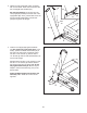
7. Insert the wires into the Left Upright (89) as you set the console assembly on the Left and Right Uprights (89, 90). Be careful not to pinch the Upright Wire (84). 7 Console Assembly Attach the console assembly with four 5/16" x 1 1/2" Screws (5) and four 5/16" Star Washers (10). Start all four Screws, and then tighten each of them. 5 10 5 84 10 90 89 8. Identify the Left Handrail (87), which is marked with a “Left” sticker.
9. Firmly tighten the four 3/8" x 2 3/4" Screws (7) first and then tighten the four 3/8" x 1 1/4" Screws (8) (only one side is shown). 9 Press the Left and Right Base Covers (92, 93) onto the Base (97) until they snap into place. 93 92 7 10. IMPORTANT: See page 14 and plug in the power cord. Next, see page 16 and turn on the power. 8 97 10 IMPORTANT: Make sure to follow all instructions in this step. Then, press the 0 percent Incline button.
. Remove the packaging material from the bottom of the Frame (56). See the inset drawing. Make sure that the 1/2" Rear Leveling Foot Nuts (111) are threaded all the way onto the Rear Leveling Feet (60). Turn the two Rear Leveling Feet all the way into the Frame. 12 56 Lower the Frame (56) (see HOW TO LOWER THE TREADMILL FOR USE on page 24).
HOW TO USE THE CHEST PULSE SENSOR HOW TO PUT ON THE CHEST PULSE SENSOR The chest pulse sensor consists of two components: the chest strap and the sensor unit. Insert the tab on one end of the chest strap into the hole in one end of the sensor unit, as shown in the inset drawing. Press the end of the sensor unit under the buckle on the chest strap. The tab should be flush with the front of the sensor unit.
OPERATION AND ADJUSTMENT THE PRE-LUBRICATED WALKING BELT Your treadmill features a walking belt coated with highperformance lubricant. IMPORTANT: Never apply silicone spray or other substances to the walking belt or the walking platform. Such substances will cause excessive wear. HOW TO PLUG IN THE POWER CORD DANGER: Improper connection dance with all local codes and ordinances. IMPORTANT: The treadmill is not compatible with GFCI-equipped outlets and may not be compatible with AFCI-equipped outlets.
CONSOLE DIAGRAM Audio Jack FEATURES OF THE CONSOLE The treadmill console offers an impressive array of features designed to make your workouts more effective and enjoyable. When you use the manual mode, you can change the speed and incline of the treadmill with the touch of a button. As you exercise, the console will display instant exercise feedback. You can even measure your heart rate using the handgrip pulse sensor or the chest pulse sensor (see page 13).
HOW TO TURN ON THE POWER IMPORTANT: If the treadmill has been exposed to cold temperatures, allow it to warm to room temperature before turning on the power. If you do not do this, you may damage the console displays or other electrical components. Plug in the power cord (see page 14). Next, locate the power switch on the treadmill frame near the power cord. Press the power switch into the reset position. Reset HOW TO USE THE MANUAL MODE 1. Insert the key into the console.
4. Change the incline of the treadmill as desired. The My Trail tab will show a track that represents 1/4 mile (400 meters). As you exercise, the flashing rectangle will show your progress. The My Trail tab will also show the number of laps you are completing. To change the incline of the treadmill, press the Incline increase or decrease button or one of the numbered 1 Step Incline buttons. Each time you press one of the buttons, the treadmill will gradually adjust to the selected incline setting.
6. Measure your heart rate if desired. Press the Manual fan button to select a fan speed or to turn off the fan. Press the Auto fan button to select the auto mode or to turn off the fan. Note: If you use the handgrip pulse sensor and the chest pulse sensor at the same time, the console will not display your heart rate accurately. For information on the chest pulse sensor, see page 13. Before using the handgrip pulse sensor, remove the sheets of plastic from the metal contacts on the pulse bar.
HOW TO USE AN ONBOARD WORKOUT During the workout, the profiles on the speed and incline tabs will Current Segment show your progress. The flashing segment of the profile represents the current segment of the workout. The height of the flashing segment indicates the speed or incline setting for the current segment. 1. Insert the key into the console. See HOW TO TURN ON THE POWER on page 16. 2. Select an onboard workout.
If the speed or incline setting is too high or too low at any time during the workout, you can manually override the setting by pressing the Speed or Incline buttons; however, when the next segment of the workout begins, the treadmill will automatically adjust to the speed and incline settings for the next segment. To stop the workout at any time, press the Stop button. The time will begin to flash in the display. To resume the workout, press the Start button or the Speed increase button.
Press the iFit Live button to download the next workout in your schedule. Press the My Trainer button, the My Maps button, the World Tour button, or the Event Training button to download the next workout of that type in your schedule. Press the Compete button to compete in a race that you have previously scheduled. For more information on the iFit Live workouts, please see www.iFit.com.
THE INFORMATION MODE The console features an information mode that keeps track of treadmill information and allows you to personalize console settings. To select the information mode, hold down the Stop button while inserting the key into the console and then release the Stop button. When the information mode is selected, the following information will be shown: The time display will show the total number of hours the treadmill has been used.
HOW TO USE THE STEREO SOUND SYSTEM To play music or audio books through the consoleʼs stereo speakers, you must connect your MP3 player, CD player, or other personal audio player to the console through the audio jack. To use the audio jack, locate the included audio wire and plug it into the audio jack near the Manual button. Then, plug the audio wire into a jack on your MP3 player, CD player, or other personal audio player. Make sure that the audio wire is fully inserted.
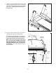
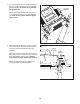
HOW TO FOLD AND MOVE THE TREADMILL HOW TO FOLD THE TREADMILL To avoid damaging the treadmill, adjust the incline to 0 percent before you fold the treadmill. Then, remove the key and unplug the power cord. CAUTION: You must be able to safely lift 45 lbs. (20 kg) to raise, lower, or move the treadmill. 1. Hold the frame firmly in the location shown by the arrow below. CAUTION: Bend your legs and keep your back straight.
TROUBLESHOOTING Most treadmill problems can be solved by following the simple steps below. Find the symptom that applies, and follow the steps listed. If further assistance is needed, see the front cover of this manual. SYMPTOM: The power does not turn on a. Make sure that the power cord is plugged into a surge suppressor and that the surge suppressor is plugged into a properly grounded outlet (see page 14).
SYMPTOM: The walking belt slows when walked on Lower the treadmill (see HOW TO LOWER THE TREADMILL FOR USE on page 24). Remove the three #8 x 3/4" Screws (1). Carefully pivot the Motor Hood (71) off. a. Use only a single-outlet surge suppressor that meets all of the specifications described on page 14. b. If the walking belt is overtightened, treadmill performance may decrease and the walking belt may become damaged. Remove the key and UNPLUG THE POWER CORD.
SYMPTOM: The walking belt is off-center or slips when walked on b. If the walking belt slips when walked on, first remove the key and UNPLUG THE POWER CORD. Using the hex key, turn both idler roller screws clockwise, 1/4 of a turn. When the walking belt is correctly tightened, you should be able to lift each edge of the walking belt 2 to 3 in. (5 to 7 cm) off the walking platform. Be careful to keep the walking belt centered.
EXERCISE GUIDELINES WARNING: Before beginning this Burning Fat—To burn fat effectively, you must exercise at a low intensity level for a sustained period of time. During the first few minutes of exercise, your body uses carbohydrate calories for energy. Only after the first few minutes of exercise does your body begin to use stored fat calories for energy. If your goal is to burn fat, adjust the intensity of your exercise until your heart rate is near the lowest number in your training zone.
SUGGESTED STRETCHES The correct form for several basic stretches is shown at the right. Move slowly as you stretch—never bounce. 1. Toe Touch Stretch Stand with your knees bent slightly and slowly bend forward from your hips. Allow your back and shoulders to relax as you reach down toward your toes as far as possible. Hold for 15 counts, then relax. Repeat 3 times. Stretches: Hamstrings, back of knees and back. 1 2. Hamstring Stretch Sit with one leg extended.
PART LIST Model No. 831.24992.2 R0211A To locate the parts listed below, see the EXPLODED DRAWING near the end of this manual. Key No. Qty. 1 2 3 4 5 6 7 8 9 10 11 12 13 14 15 16 17 18 19 20 21 22 23 24 25 26 27 28 29 30 31 32 33 34 35 36 37 38 39 40 41 42 43 44 45 46 47 48 49 50 84 2 1 4 4 1 4 4 7 10 2 4 11 1 4 2 1 2 8 2 9 2 2 2 2 2 16 1 1 4 2 6 2 6 10 3 1 2 1 1 1 8 1 1 1 2 2 4 1 1 Description Key No. Qty.
Key No. Qty. 101 102 103 104 105 106 107 108 2 1 1 1 1 2 1 1 Description Key No. Qty. Wheel Console Base Console Console Back Fan Assembly Handrail Spacer Console Frame Pulse Bar Top 109 110 111 112 113 114 * 1 1 2 2 1 1 – Description Pulse Ground Wire Pulse Bar Bottom 1/2" Rear Leveling Foot Nut 3/8" Flat Washer Short Hex Key #8 x 3/8” Screw Userʼs Manual Note: Specifications are subject to change without notice. For information about ordering replacement parts, see the back cover of this manual.
1 113 16 41 1 1 58 1 25 63 65 111 27 39 59 31 35 58 37 61 1 1 38 27 27 60 1 66 69 16 1 68 42 43 32 35 42 45 44 1 42 1 27 59 31 35 25 1 32 35 62 42 35 32 1 60 111 66 27 42 35 32 21 40 1 1 38 46 1 11 1 58 1 47 58 32 35 6 26 35 23 27 42 1 51 13 1 32 35 42 57 27 56 49 50 55 1 20 52 1 1 27 42 53 46 9 21 48 26 22 11 3 54 1 47 35 28 29 23 9 20 EXPLODED DRAWING A Model No. 831.24992.
EXPLODED DRAWING B Model No. 831.24992.
EXPLODED DRAWING C Model No. 831.24992.
EXPLODED DRAWING D Model No. 831.24992.
ORDERING REPLACEMENT PARTS To order replacement parts, please see the front cover of this manual.