
Owner's Manual

10
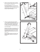
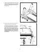
8. Identify the Left Handrail (87), which is marked
with a “Left” sticker. Slide the Left Handrail be-
tween the console assembly and the pulse
assembly.
Attach the Left Handrail (87) with two 5/16" x 2"
Screws (4), a 5/16" x 3 3/4" Screw (2), and three
5/16" Star Washers (10) as shown. Start all
three Screws, and then tighten each of them.
Attach the Right Handrail (not shown) to the
console assembly as described above.
10
4
Console
Assembly
Pulse
Assembly
8
87
10
4
2
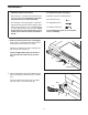
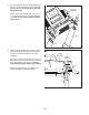
7. Insert the wires into the Left Upright (89) as you
set the console assembly on the Left and Right
Uprights (89, 90). Be careful not to pinch the
U
pright Wire (84).
A
ttach the console assembly with four 5/16" x
1 1/2" Screws (5) and four 5/16" Star Washers
(10). Start all four Screws, and then tighten
each of them.
7
89
90
5
10
84
10
5
C
onsole
Assembly