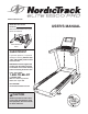
www.nordictrack.com Model No. NTL17010.2 Serial No. Write the serial number in the space above for reference. Serial Number Decal QUESTIONS? If you have questions, or if parts are damaged or missing, DO NOT CONTACT THE STORE; please contact Customer Care. IMPORTANT: Please register this product (see the limited warranty on the back cover of this manual) before contacting Customer Care. 1-800-TO-BE-FIT CALL TOLL-FREE: (1-800-862-3348) Mon.–Fri. 6 a.m.–6 p.m. MT Sat. 8 a.m.–4 p.m. MT ON THE WEB: www.
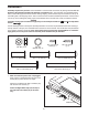
TABLE OF CONTENTS WARNING DECAL PLACEMENT . . . . . . . . . . . . . . . . . . . . . . . . . . . . . . . . . . . . . . . . . . . . . . . . . . . . . . . . . . . . . .2 IMPORTANT PRECAUTIONS . . . . . . . . . . . . . . . . . . . . . . . . . . . . . . . . . . . . . . . . . . . . . . . . . . . . . . . . . . . . . . . .3 BEFORE YOU BEGIN . . . . . . . . . . . . . . . . . . . . . . . . . . . . . . . . . . . . . . . . . . . . . . . . . . . . . . . . . . . . . . . . . . . . . .5 ASSEMBLY . . . . . . . . . . . . .
IMPORTANT PRECAUTIONS WARNING: To reduce the risk of serious injury, read all important precautions and instructions in this manual and all warnings on your treadmill before using your treadmill. ICON assumes no responsibility for personal injury or property damage sustained by or through the use of this product. 1. Before beginning any exercise program, consult your physician. This is especially important for persons over age 35 or persons with pre-existing health problems. carrying 15 or more amps.
24. Inspect and properly tighten all parts of the treadmill regularly. 20. Never leave the treadmill unattended while it is running. Always remove the key, unplug the power cord, and press the power switch into the off position when the treadmill is not in use. (See the drawing on page 5 for the location of the power switch.) 25. 21. Do not attempt to raise, lower, or move the treadmill until it is properly assembled. (See ASSEMBLY on page 6, and HOW TO FOLD AND MOVE THE TREADMILL on page 29.
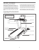
BEFORE YOU BEGIN Thank you for selecting the revolutionary NORDICTRACK® ELITE 9500 PRO treadmill. The ELITE 9500 PRO treadmill offers an impressive selection of features designed to make your workouts at home more enjoyable and effective. And when youʼre not exercising, the unique treadmill can be folded up, requiring less than half the floor space of other treadmills. ing this manual, please see the front cover of this manual.
ASSEMBLY Assembly requires two persons. Set the treadmill in a cleared area and remove all packing materials. Do not dispose of the packing materials until assembly is completed. Note: The underside of the treadmill walking belt is coated with high-performance lubricant. During shipping, some lubricant may be transferred to the top of the walking belt or the shipping carton. This is normal and does not affect treadmill performance.
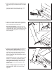
2. Pull the Upright Wire (84) and the Base Ground Wire (94) through the indicated hole in the Base (97). 2 Attach the Base Ground Wire (94) to the Base (97) with a #8 x 1/2" Ground Screw (9). Hole 84 94 9 3. Identify the Left Upright (89), which is marked with a “Left” sticker. Have a second person hold the Left Upright near the Base (97). 3 84 See the inset drawing. Tie the wire tie in the Left Upright (89) securely around the end of the Upright Wire (84).
5. Identify the Left and Right Base Covers (92, 93). Slide the Left Base Cover onto the Left Upright (89). Slide the Right Base Cover onto the Right Upright (90). Do not press the Base Covers into place yet. 5 90 89 93 92 6. Set the handrail assembly face down on a soft surface to avoid scratching the handrail assembly. 6 Remove two 3/8" x 2" Screws (3) and a Handrail Bracket (85) from each side of the handrail assembly.
7. Remove the four 3/8" x 1" Screws (2) from the Uprights (89, 90). 7 Orient each Handrail Bracket (85) so that the long tab is in the position shown and the large holes are on top. Route the Upright Wire (84) through the center hole in a Handrail Bracket. Long Tab Attach each Handrail Bracket (85) with the two 3/8" x 1" Screws (2) and two 3/8" Star Washers (12). Start all four Screws, and then tighten each of them. 84 8.
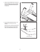
9. Insert the wires into the Left Upright (89) as you set the handrail assembly on the Left and Right Uprights (89, 90). Be careful not to pinch the wires. 9 Handrail Assembly Attach the handrail assembly with the four 3/8" x 2" Screws (3) that you removed in step 6 and four 3/8" Star Washers (12). Start all four Screws, and then tighten each of them. Wires 12 12 3 3 89 90 10. With the help of a second person, hold the console assembly near the handrail assembly.
. Firmly tighten the four 3/8" x 2 3/4" Screws (7) first, and then tighten the four 3/8" x 1 1/4" Screws (8) (only one side is shown). 11 Press the Left and Right Base Covers (92, 93) onto the Base (97) until they snap into place. 92 7 12. IMPORTANT: See page 14 and plug in the power cord. Next, see page 16 and turn on the power. 93 8 97 12 IMPORTANT: Make sure to follow all instructions in this step. Then, press the 0 percent Incline button.
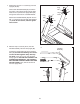
14. Remove the packaging material from the bottom of the Frame (56). See the inset drawing. Make sure that the 1/2" Rear Leveling Foot Nuts (30) are threaded all the way onto the Rear Leveling Feet (60). Turn the two Rear Leveling Feet all the way into the Frame. 14 56 Lower the Frame (56) (see HOW TO LOWER THE TREADMILL FOR USE on page 29).
HOW TO USE THE CHEST PULSE SENSOR HOW TO PUT ON THE CHEST PULSE SENSOR The chest pulse sensor consists of two components: the chest strap and the sensor unit. Insert the tab on one end of the chest strap into the hole in one end of the sensor unit, as shown in the inset drawing. Press the end of the sensor unit under the buckle on the chest strap. The tab should be flush with the front of the sensor unit.
OPERATION AND ADJUSTMENT THE PRE-LUBRICATED WALKING BELT The treadmill features a walking belt coated with highperformance lubricant. IMPORTANT: Never apply silicone spray or other substances to the walking belt or the walking platform. Such substances will cause excessive wear. HOW TO PLUG IN THE POWER CORD DANGER: Improper connection dance with all local codes and ordinances. IMPORTANT: The treadmill is not compatible with GFCI-equipped outlets and may not be compatible with AFCI-equipped outlets.
CONSOLE DIAGRAM FEATURES OF THE CONSOLE The treadmill console offers an impressive array of features designed to make your workouts more effective and enjoyable. The console features revolutionary iFit Live technology that enables the treadmill to communicate with your wireless network. With iFit Live technology, you can download personalized workouts, create your own workouts, track your workout results, and access many other features. See www.iFit.com for complete information.
HOW TO TURN ON THE POWER HOW TO SET UP THE CONSOLE IMPORTANT: If the treadmill has been exposed to cold temperatures, allow it to warm to room temperature before you turn on the power. If you do not do this, you may damage the console display or other electrical components. Plug in the power cord (see page 14). Next, locate the power switch on the treadmill frame near the power cord. Make sure that the switch is in the reset position. Before using the treadmill for the first time, set up your console. 1.
HOW TO USE THE MANUAL MODE The browser will open to the iFit.com home page. Touch the Register Now button in the upper-right corner of the screen. 1. Insert the key into the console. The browser will open to the iFit.com registration page. Touch an entry box to view the keyboard. Slide your finger up or down the screen to scroll up or down the page. See HOW TO TURN ON THE POWER on page 16. Note: It may take a minute for the console to be ready for use. 2. Select the main menu.
4. Change the incline of the treadmill as desired. • The number of vertical feet you have climbed To change the incline of the treadmill, press the Incline increase and decrease buttons or one of the numbered 1 Step Incline/Decline buttons. Each time you press one of the buttons, the incline will gradually change until it reaches the selected incline setting. • Your heart rate (see step 6 on page 19) The displays at the top of the screen can show two types of information.
6. Measure your heart rate if desired. speed of the fan will automatically increase and decrease as the speed of the walking belt increases and decreases. Note: If you use the handgrip pulse sensor and the chest pulse sensor at the same time, the console will not display your heart rate accurately. For information about the chest pulse sensor, see page 13. Before using the handgrip pulse sensor, remove the sheets of plastic from the metal contacts on the pulse bar.
HOW TO USE AN ONBOARD WORKOUT and/or incline setting may be programmed for consecutive segments. 1. Insert the key into the console. During the workout, the profile will show your progress. Touch the Display increase and decrease buttons repeatedly to view the profile. The colored line will indicate the current segment of the workout. The colored profile represents the incline setting of the current segment. The black line represents the speed setting of the current segment. See step 1 on page 17. 2.
Note: The calorie goal is an estimate of the number of calories that you will burn during the workout. The actual number of calories that you burn will depend on your weight. In addition, if you manually change the speed or incline of the treadmill during the workout, the number of calories you burn will be affected. HOW TO USE AN IFIT LIVE WORKOUT Note: To use an iFit Live workout, you must have access to a wireless network including an 802.
When you select an iFit Live workout, the screen will show the name, duration, and distance of the workout. The screen will also show the approximate number of calories you will burn during the workout. If you select a competition workout, the display will count down to the beginning of the race. 5. Start the workout. See step 4 on pages 20 and 21. During some workouts, the voice of a personal trainer will guide you through your workout. 6. Monitor your progress. See step 5 on page 18.
HOW TO USE THE INTERNET BROWSER Note: To use the browser, you must have access to a wireless network including an 802.11b/n router with SSID broadcast enabled (hidden networks are not supported). To open the browser, touch the globe button near the lower left corner of the screen. Then, select a website. Navigate through the browser using the back button, the menu button, and the home button on the console. Back Menu Home Press the back button to return to the previous web page.
HOW TO USE THE SETTINGS MODE An information box will ask if you want to connect to the wireless network. Touch the Connect button to connect to the network or touch the Cancel button to return to the list of networks. If the network has a password, touch the password entry box. A keyboard will appear on the screen. To view the password as you type it, touch the Show Password checkbox.
3. Log in to your iFit Live account. 6. Turn on or turn off the display demo mode. To log in to an iFit Live account, touch the iFit Live Login button. Then, enter your user name and password using the keyboard on the screen. See step 2 on page 24 for instructions about using the keyboard. When you are finished, touch the Submit button or touch the Cancel button to return to the settings mode. Note: To switch users within an iFit Live account, see step 4 on page 21.
HOW TO USE THE MAINTENANCE MODE The console features a maintenance mode that allows you to calibrate the incline and speed of the treadmill, update the console firmware, calibrate the screen, view technical information, and perform a network test. 1. Select the settings mode. See step 1 on page 24. 2. Select the maintenance mode. 4. Calibrate the speed of the treadmill. Calibrate the speed of the treadmill only if instructed to do so by an authorized service representative.
6. Calibrate the screen. If the screen is not properly calibrated, it will be difficult for you to touch the correct buttons on the screen. To calibrate the screen, touch the Calibrate Screen button and then touch the Begin button. A small target will appear on the screen. Note: Touch the Cancel button to return to the maintenance mode. Using a pencil eraser or other small object, touch the center of the target. Then, touch the rest of the targets.
HOW TO USE THE STEREO SOUND SYSTEM HOW TO ADJUST THE CUSHIONING SYSTEM Remove the key from the console and unplug the power cord. The treadmill features a cushioning system that reduces the impact as you walk or run on the treadmill. To play music or audio books through the consoleʼs speakers, you must connect your MP3 player, CD player, or other personal audio player to the console. Locate the audio wire. Plug one end into the audio jack on the side of the console.
HOW TO FOLD AND MOVE THE TREADMILL HOW TO FOLD THE TREADMILL HOW TO MOVE THE TREADMILL To avoid damaging the treadmill, adjust the incline to zero percent before you fold the treadmill. Then, remove the key and unplug the power cord. CAUTION: You must be able to safely lift 45 lbs. (20 kg) to raise, lower, or move the treadmill. Before moving the treadmill, fold it as described at the left. CAUTION: Make sure that the latch knob is locked in the storage position.
TROUBLESHOOTING Most treadmill problems can be solved by following the simple steps below. Find the symptom that applies, and follow the steps listed. If further assistance is needed, see the front cover of this manual. SYMPTOM: The console displays remain lit when you remove the key from the console a. The console features a display demo mode, designed to be used if the treadmill is displayed in a store. If the screen shows a demo presentation when you remove the key, the demo mode is turned on.
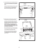
SYMPTOM: The iFit Live mode does not function correctly Lower the treadmill (see HOW TO LOWER THE TREADMILL FOR USE on page 29). Remove the three #8 x 3/4" Screws (1). Carefully pivot the Motor Hood (71) off. 71 a. If the iFit Live mode is not functioning correctly, make sure that the treadmill has the most current firmware available (see step 5 on page 26). 1 SYMPTOM: The walking belt slows when walked on a.
SYMPTOM: The walking belt is off-center or slips when walked on SYMPTOM: The treadmill will not connect to the wireless network a. If the walking belt is off-center, first remove the key and UNPLUG THE POWER CORD. If the walking belt has shifted to the left, use the hex key to turn the left idler roller screw clockwise 1/2 of a turn; if the walking belt has shifted to the right, turn the left idler roller screw counterclockwise 1/2 of a turn. Be careful not to overtighten the walking belt.
EXERCISE GUIDELINES WARNING: Before beginning this Burning Fat—To burn fat effectively, you must exercise at a low intensity level for a sustained period of time. During the first few minutes of exercise, your body uses carbohydrate calories for energy. Only after the first few minutes of exercise does your body begin to use stored fat calories for energy. If your goal is to burn fat, adjust the intensity of your exercise until your heart rate is near the lowest number in your training zone.
PART LIST Model No. NTL17010.2 R0211A To locate the parts listed below, see the EXPLODED DRAWING near the end of this manual. Key No. Qty. 1 2 3 4 5 6 7 8 9 10 11 12 13 14 15 16 17 18 19 20 21 22 23 24 25 26 27 28 29 30 31 32 33 34 35 36 37 38 39 40 41 42 43 44 45 46 47 48 49 50 59 4 5 2 10 1 4 4 8 1 2 14 21 1 12 2 1 2 6 2 4 2 2 2 2 2 16 1 1 2 2 1 2 6 6 3 1 16 1 1 1 4 1 1 1 2 2 4 1 1 Description Key No. Qty.
Key No. Qty. 101 102 103 104 105 106 107 2 1 1 2 2 1 1 Description Key No. Qty. Wheel Handrail Top Console Cushion Adjust Assembly #1 Cushion Adjust Assembly #2 Hex Key Handrail Frame 108 109 110 111 112 113 * 1 1 2 2 2 2 – Description Pulse Bar Top Pulse Ground Wire Front Cushion 5/16" Cushion Washer 3/8" Flat Washer Bumper Userʼs Manual Note: Specifications are subject to change without notice. For information about ordering replacement parts, see the back cover of this manual.
5 58 5 106 16 13 37 35 13 61 65 30 27 59 31 63 25 15 113 5 35 60 66 42 5 15 39 69 43 16 41 13 5 38 44 59 31 35 13 25 110 35 66 5 30 60 27 42 27 104 45 13 15 111 21 15 13 40 105 38 46 1 13 38 47 15 58 27 15 27 105 26 35 23 51 13 13 49 57 56 38 104 27 50 27 42 110 20 52 13 27 9 113 15 1 46 111 21 42 48 22 26 62 47 35 13 28 29 9 68 15 23 20 EXPLODED DRAWING A Model No. NTL17010.
EXPLODED DRAWING B Model No. NTL17010.
EXPLODED DRAWING C 2 Model No. NTL17010.
EXPLODED DRAWING D 95 Model No. NTL17010.
ORDERING REPLACEMENT PARTS To order replacement parts, please see the front cover of this manual.