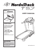
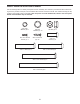
Model No. 29836.1 Serial No. Write the serial number in the space above for reference. USER’S MANUAL Serial Number Decal QUESTIONS? If you have questions, or if parts are damaged or missing, PLEASE CONTACT OUR CUSTOMER SERVICE DEPARTMENT DIRECTLY. CALL TOLL-FREE: 1-888-936-4266 Mon.–Fri., 7:30 until 16:30 ET (excluding holidays) OR E-MAIL US: customerservice@iconcanada.ca CAUTION Read all precautions and instructions in this manual before using this equipment. Keep this manual for future reference.
TABLE OF CONTENTS WARNING DECAL PLACEMENT . . . . . . . . . . . . . . . . . . . . . . . . . . . . . . . . . . . . . . . . . . . . . . . . . . . . . . . . . . . . . . 2 IMPORTANT PRECAUTIONS. . . . . . . . . . . . . . . . . . . . . . . . . . . . . . . . . . . . . . . . . . . . . . . . . . . . . . . . . . . . . . . . . 3 BEFORE YOU BEGIN. . . . . . . . . . . . . . . . . . . . . . . . . . . . . . . . . . . . . . . . . . . . . . . . . . . . . . . . . . . . . . . . . . . . . . . 5 PART IDENTIFICATION CHART. . .
IMPORTANT PRECAUTIONS WARNING: To reduce the risk of serious injury, read all important precations and instructions in this manual and all warnings on your treadmill before using your treadmill. ICON assumes no responsibility for personal injury or property damage sustained by or through the use of this product. 1. Before beginning any exercise program, consult your physician. This is especially important for persons over age 35 or persons with pre-existing health problems.
DANGER 20. Never leave the treadmill unattended while it is running. Always remove the key, unplug the power cord, and press the power switch into the off position when the treadmill is not in use. (See the drawing on page 5 for the location of the power switch.) 25. : Always unplug the power cord immediately after use, before cleaning the treadmill, and before performing the maintenance and adjustment procedures described in this manual.
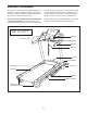
BEFORE YOU BEGIN Thank you for selecting the new NORDICTRACK® T5.7 treadmill. The T5.7 treadmill provides an impressive selection of features designed to make your workouts at home more effective and enjoyable. manual. To help us assist you, note the product model number and serial number before contacting us. The model number and the location of the serial number decal are shown on the front cover of this manual. For your benefit, read this manual carefully before you use the treadmill.
PART IDENTIFICATION CHART Use the drawings below to identify small parts used for assembly. The number in parentheses below each drawing is the key number of the part, from the PART LIST near the end of this manual. The number following the key number is the quantity used for assembly. Note: If a part is not in the hardware kit, check to see if it is preattached. Extra hardware may be included.
ASSEMBLY • Assembly requires two persons. • Assembly requires the following tools: • Place all parts in a cleared area and remove the packing materials. Do not dispose of the packing materials until you finish all assembly steps. the included hex keys • The underside of the walking belt is coated with high-performance lubricant. After shipping, there may be some lubricant on top of the walking belt or on the shipping carton. This is normal.
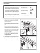
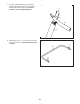
3. Identify the Left Upright (75), which is marked “Left.” Have a second person hold the Left Upright near the Base (80). 3 75 See the inset drawing. Tie the wire tie in the Left Upright (75) securely around the end of the Upright Wire (70). Then, insert the Upright Wire into the lower end of the Left Upright as you pull the other end of the wire tie through the Left Upright. 70 Wire Tie 80 75 Wire Tie 4. With the help of a second person, hold the Left Upright (75) against the Base (80).
5. With the help of a second person, tip treadmill so that the Base (80) is flat on the ground. 5 Identify the Left and Right Base Covers (73, 74), which are marked “L” and “R.” Slide the Left and Right Base Covers onto the Left and Right Uprights (75, 76) as shown. 76 70 74 75 73 6. Identify the Left Handrail (71), which is marked “Left.” If there is a wire in the Left Handrail, remove and discard it. 80 6 9 70 Hold the Left Handrail (71) near the Left Upright (75).
7. Attach the Right Handrail (72) to the Right Upright (76) with two 3/8" x 3 1/2" Screws (9) and two 3/8" Star Washers (5). Start both Screws, but do not tighten them yet. 7 9 5 72 76 8. Remove the four 1/4" x 1" Screws (10) from the Console Frame (87). The Screws will be used in step 9.
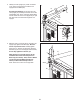
9. Insert the Console Frame (87) into the Handrails (71, 72). Attach the Console Frame with the four 1/4" x 1" Screws (10) that you removed in step 8. Start all four Screws, and then tighten them. Be careful not to pinch the Upright Wire (not shown). 9 87 9 Firmly tighten the four 3/8" x 3 1/2" Screws (9). 10 72 9 10 10. With the help of a second person, hold the console assembly near the Left Handrail (71) and the Right Handrail (not shown).
11. Set the console assembly on the Left and Right Handrails (71, 72). Make sure that no wires are pinched. Insert the excess Upright Wire (70) into the Left Handrail. 11 Console Assembly Attach the console assembly to the brackets on the Handrails (71, 72) with two 5/16" x 1" Screws (7) and two 5/16" Star Washers (8). Start both Screws, and then tighten them. 87 72 12. Attach the two Console Clamps (96) to the console assembly with four #8 x 3/4" Screws (6).
14. Raise the Frame (49) to the position shown. Have a second person hold the Frame until this step is completed. 14 49 Orient the Storage Latch (51) so that the large barrel and the latch knob are oriented as shown. Attach the lower end of the Storage Latch (51) to the Base (80) with a 3/8" x 2" Bolt (12) and a 3/8" Nut (3). 3 Attach the upper end of the Storage Latch (51) to the Frame (49) with a 3/8" x 2" Bolt (12) and a 3/8" Nut (3).
OPERATION AND ADJUSTMENT HOW TO PLUG IN THE POWER CORD This product is for use on a nominal 120-volt circuit (see drawing 1). A temporary adapter may be used to connect the surge suppressor to a 2-pole receptacle if a properly-grounded outlet is not available (see drawing 2). DANGER: Improper connection of the equipment-grounding conductor increases the risk of electric shock. Check with a qualified electrician or serviceman if you are unsure whether the product is properly grounded.
CONSOLE DIAGRAM FEATURES OF THE CONSOLE The treadmill console offers an impressive array of features designed to make your workouts more effective and enjoyable. When the manual mode of the console is selected, you can change the speed and incline of the treadmill with the touch of a button. As you exercise, the console will display instant exercise feedback. You can even measure your heart rate using the handgrip heart rate monitor.
599611 4985) HOW TO TURN ON THE POWER HOW TO USE THE MANUAL MODE IMPORTANT: If the treadmill has been exposed to cold temperatures, allow it to warm to room temperature before turning on the power. If you do not do this, you may damage the console displays or other electrical components. 1. Insert the key into the console. Plug in the power cord (see page 14). Next, locate the power switch on the treadmill frame near the power cord. Make sure that the switch is in the reset position.
4. Change the incline of the treadmill as desired. he Speed tab will show a profile of the speed setT tings of the workout. To change the incline of the treadmill, press the Incline increase or decrease button or one of the numbered Quick Incline buttons. Each time you press one of the buttons, the treadmill will gradually adjust to the selected incline setting. The My Trail tab will show a track that represents 1/4 mile (400 m). As you exercise, the flashing rectangle will show your progress.
6. Measure your heart rate if desired. Before using the heart rate monitor, remove the sheets of plastic from the metal contacts, if necessary. In addition, make sure that your hands are clean. hen you are finished using the treadmill, press W the power switch into the off position and unplug the power cord. IMPORTANT: If you do not do this, the treadmill’s electrical components may wear prematurely.
HOW TO USE AN ONBOARD WORKOUT The workout will continue in this way until the last segment of the profile flashes in the display and the last segment ends. The walking belt will then slow to a stop. 1. Insert the key into the console. See HOW TO TURN ON THE POWER on page 16. Note: The calorie goal is an estimate of the number of calories that you will burn during the workout. The actual number of calories that you burn will depend on your metabolic rate.
HOW TO USE AN IFIT LIVE WORKOUT calories you will burn. The display may also show the name of the workout. If you select a competition workout, the display will count down to the beginning of the race. Note: To use an iFit Live workout, you must have an optional iFit Live module. To purchase an iFit Live module at any time, go to www.iFit.com or call the telephone number on the front cover of this manual. You must also have access to a computer with a USB port and an internet connection.
THE INFORMATION MODE 3. CONTRAST LVL: Press the Incline increase and decrease buttons to adjust the contrast level of the display. The console features an information mode that keeps track of treadmill information and allows you to personalize console settings. If a module is connected, you may also select the following screen: To select the information mode, hold down the Stop button while inserting the key into the console and then release the Stop button.
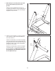
HOW TO FOLD AND MOVE THE TREADMILL HOW TO FOLD THE TREADMILL HOW TO MOVE THE TREADMILL To avoid damaging the treadmill, adjust the incline to the lowest position before you fold the treadmill. Then, remove the key and unplug the power cord. CAUTION: You must be able to safely lift 45 lbs. (20 kg) to raise, lower, or move the treadmill. efore moving the treadmill, fold it as described at the B left. CAUTION: Make sure that the latch knob is locked in the storage position.
TROUBLESHOOTING Most treadmill problems can be solved by following the simple steps below. Find the symptom that applies, and follow the steps listed. If further assistance is needed, see the front cover of this manual. c. Remove the key from the console, and then reinsert it. d. If the treadmill still will not run, please see the front cover of this manual. SYMPTOM: The power does not turn on SYMPTOM: The console displays remain lit when you remove the key from the console a.
Locate the Reed Switch (95) and the Magnet (44) on the left side of the Pulley (43). Turn the Pulley until the Magnet is aligned with the Reed Switch. Make sure that the gap between the Magnet and the Reed Switch is about 1/8 in. (3 mm). If necessary, loosen the #8 x 3/4" Truss Head Screw (19), move the Reed Switch slightly, and then retighten the Screw.
SYMPTOM: The walking belt is off-center or slips when walked on b. I f the walking belt slips when walked on, first remove the key and UNPLUG THE POWER CORD. Using the hex key, turn both idler roller screws clockwise, 1/4 of a turn. When the walking belt is correctly tightened, you should be able to lift each edge of the walking belt 2 to 3 in. (5 to 7 cm) off the walking platform. Be careful to keep the walking belt centered.
EXERCISE GUIDELINES Burning Fat—To burn fat effectively, you must exercise at a low intensity level for a sustained period of time. During the first few minutes of exercise, your body uses carbohydrate calories for energy. Only after the first few minutes of exercise does your body begin to use stored fat calories for energy. If your goal is to burn fat, adjust the intensity of your exercise until your heart rate is near the lowest number in your training zone.
PART LIST Key No. Qty. 1 2 3 4 5 6 7 8 9 10 11 12 13 14 15 16 17 18 19 20 21 22 23 24 25 26 27 28 29 30 31 32 33 34 35 36 37 38 39 40 41 42 43 44 45 46 47 48 49 50 51 52 4 2 4 6 10 46 2 2 4 4 10 2 2 2 2 2 2 3 21 2 4 2 2 4 2 2 2 2 2 1 1 1 8 1 1 4 1 1 1 1 2 2 1 1 1 1 1 2 1 1 1 1 Model No. 29836.1 R0811A Description Key No. Qty.
14 28 53 34 19 26 19 36 19 35 25 56 19 38 19 36 19 52 39 14 19 19 19 25 19 37 24 40 41 26 19 19 42 28 3 19 36 19 19 29 44 43 12 103 27 95 45 36 19 23 19 50 16 1 19 46 51 24 48 19 41 47 27 42 28 29 30 32 49 48 3 16 12 EXPLODED DRAWING A Model No. 29836.
EXPLODED DRAWING B Model No. 29836.
EXPLODED DRAWING C Model No. 29836.
EXPLODED DRAWING D Model No. 29836.
ORDERING REPLACEMENT PARTS To order replacement parts, please see the front cover of this manual.