Model No. NTL06907.2 Serial No. USER'S MANUAL Write the serial number in the space above for reference. Serial Number Decal QUESTIONS? As a manufacturer, we are committed to providing complete customer satisfaction. If you have questions, or if parts are damaged or missing, PLEASE CONTACT OUR CUSTOMER SERVICE DEPARTMENT DIRECTLY. CALL TOLL-FREE: 1-888-825-2588 Mon.–Fri. 6 a.m.–6 p.m. MST Sat. 8 a.m.–4 p.m. MST ON THE WEB: www.nordictrackservice.
TABLE OF CONTENTS WARNING DECAL PLACEMENT . . . . . . . . . . . . . . . . . . . . . . . . . . . . . . . . . . . . . . . . . . . . . . . . . . . . . . . . . . . . . .2 IMPORTANT PRECAUTIONS . . . . . . . . . . . . . . . . . . . . . . . . . . . . . . . . . . . . . . . . . . . . . . . . . . . . . . . . . . . . . . . .3 BEFORE YOU BEGIN . . . . . . . . . . . . . . . . . . . . . . . . . . . . . . . . . . . . . . . . . . . . . . . . . . . . . . . . . . . . . . . . . . . . . .5 ASSEMBLY . . . . . . . . . . . . . .
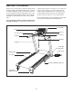
IMPORTANT PRECAUTIONS WARNING: To reduce the risk of serious injury, read all important precautions and instructions in this manual and all warnings on your treadmill before using your treadmill. ICON assumes no responsibility for personal injury or property damage sustained by or through the use of this product. 1. Before beginning any exercise program, consult your physician. This is especially important for persons over the age of 35 or persons with pre-existing health problems.
24. Inspect and properly tighten all parts of the treadmill regularly. 20. Never leave the treadmill unattended while it is running. Always remove the key, unplug the power cord, and switch the reset/off circuit breaker to the off position when the treadmill is not in use. (See the drawing on page 5 for the location of the circuit breaker.) 25. 21. Do not attempt to raise, lower, or move the treadmill until it is properly assembled.
BEFORE YOU BEGIN Thank you for selecting the revolutionary NordicTrack® A2105 treadmill. The A2105 treadmill offers a selection of features designed to make your workouts at home more enjoyable and effective. And when you’re not exercising, the unique A2105 treadmill can be folded up, requiring less than half the floor space of other treadmills. ing this manual, please see the front cover of this manual. To help us assist you, note the product model number and serial number before contacting us.
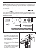
ASSEMBLY Assembly requires two persons. Set the treadmill in a cleared area and remove all packing materials. Do not dispose of the packing materials until assembly is completed. Note: The underside of the treadmill walking belt is coated with high-performance lubricant. During shipping, a small amount of lubricant may be transferred to the top of the walking belt or the shipping carton. This is a normal condition and does not affect treadmill performance.
2. Remove the 3/8" Nut (8), the 3/8" x 2" Bolt (4), and the shipping bracket (C) from the Base (83). Attach a Wheel (84) with the Bolt and the Nut that you just removed. Do not overtighten the Nut; the Wheel must turn freely. Discard the shipping bracket. 2 Tie 38 83 Cut the tie off the Upright Wire (38). 4 84 C 8 3. Identify the Right Upright (78) and the Right Upright Spacer (79), which are marked with stickers. Insert the Upright Wire (38) through the Right Upright Spacer as shown.
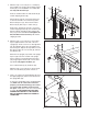
5. With the help of a second person, carefully tip the treadmill onto its right side. Partially fold the Frame (56) so the treadmill is more stable; do not fully fold the Frame yet. 5 B A Remove and discard the two indicated bolts (A) and the shipping bracket (B). 83 56 81 Attach a Base Pad (81) to the Base (83) in the location shown with a 1" Tek Screw (2) and a Base Pad Spacer (13). Then, attach another Base Pad (81) with only a 1" Tek Screw (2).
8. Insert the indicated connectors into the Right Upright (78). 8 95 Next, insert the fronts of the brackets on the Bridge (95) into the Uprights (74, 78), and then fully insert the brackets. Make sure that the plastic edges of the Bridge (95) are inside the Uprights. Connectors 10 Attach the Bridge (95) with six 1/4" x 1/2" Bolts (7) and six 1/4" Star Washers (10); start all six Bolts and then tighten them. 7 Front 7 Edge 7 See steps 4 and 6. Tighten the four 3/8" x 4 1/2" Bolts (6).
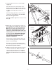
11. Raise the Frame (56) to the position shown. Have a second person hold the Frame until this step is completed. 11 56 Orient the Storage Latch (53) so that the large barrel and the Latch Knob (54) are in the positions shown. Attach the lower end of the Storage Latch to the bracket on the Base (83) with a 3/8" x 2" Bolt (4) and a 3/8" Nut (8). 8 4 53 Attach the upper end of the Storage Latch (53) to the bracket on the Frame (56) with a 3/8" x 2" Bolt (4) and a 3/8" Nut (8).
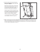
If you purchase the optional chest pulse sensor (see page 23), follow the steps below to install the receiver included with the chest pulse sensor. 1. Make sure that the power cord is unplugged. Remove the indicated 1/2" Screws (1) and the Access Door (87) from the Console Back (91). 2. Connect the wire on the receiver (A) to the indicated wire extending from the Console Back (91). Hold the receiver so the small cylinder is oriented and is facing the Console Back.
OPERATION AND ADJUSTMENT THE PRE-LUBRICATED WALKING BELT tric shock. This product is equipped with a cord having an equipment-grounding conductor and a grounding plug. Plug the power cord into a surge suppressor, and plug the surge suppressor into an appropriate outlet that is properly installed and grounded in accordance with all local codes and ordinances. Important: The treadmill is not compatible with GFCI-equipped outlets. Your treadmill features a walking belt coated with highperformance lubricant.
CONSOLE DIAGRAM Select Button Navigation Buttons Key FEATURES OF THE CONSOLE This revolutionary treadmill console offers a selection of features designed to make your workouts more effective and enjoyable. When you use the manual mode of the console, you can change the speed and incline of the treadmill with the touch of a button. As you exercise, the console will display continuous exercise feedback.
HOW TO TURN ON THE POWER When you select the user mode, the word LOGIN will appear in the display for a few seconds and then the user mode menu will appear. IMPORTANT: If the treadmill has been exposed to cold temperatures, allow it to warm to room temperature before turning on the power. If you do not do this, the console displays or other electrical components may become damaged. Plug in the power cord (see page 12). Next, locate the reset/off circuit breaker on the treadmill frame near the power cord.
To set the date, first press the left and right Navigation buttons to highlight the month, day, or year field. Then, press the up and down Navigation buttons to select the desired month, day, or year. To exit the user information menu, press the Back button. The setup menu will then appear in the display. 3. Select a default user setting. When you have finished setting the date, press the Select button. The time setting will then appear in the display.
6. Follow your progress with the display. HOW TO USE THE MANUAL MODE 1. Insert the key into the console. As you walk or run on the treadmill, the display can show the following workout information: See HOW TO TURN ON THE POWER on page 14. • The elapsed time. 2. Personalize console settings if desired. • The distance that you have walked or run. See HOW TO PERSONALIZE CONSOLE SETTINGS on page 14. • The speed of the walking belt. • The incline level of the treadmill. 3. Select the manual mode.
7. Measure your heart rate if desired. HOW TO USE A PRESET WORKOUT OR A WEIGHT LOSS WORKOUT You can measure your heart rate using either the handgrip pulse sensor or the optional chest pulse sensor (see page 23 for information about the optional chest pulse sensor). Note: If you hold the handgrip pulse sensor and wear the chest pulse sensor at the same time, the console will not display your heart rate accurately. 1. Insert the key into the console. See HOW TO TURN ON THE POWER on page 14. 2.
4. Press the Start button to start the workout. The workout will continue in this way until the small arrow reaches the right end of the profile. The walking belt will then slow to a stop. A moment after you press the Start button, the treadmill will automatically adjust to the first speed and incline settings of the workout. Hold the handrails and begin walking.
HOW TO CREATE A LEARN WORKOUT 4. Press the Start button to start the workout, and program the desired settings. 1. Insert the key into the console. Each learn workout can have up to 40 one-minute segments. You can program one speed setting and one incline setting for each segment. See HOW TO TURN ON THE POWER on page 14. 2. Select the workout menu. To program a speed setting for the first segment, press the Speed + and – buttons or one of the numbered speed buttons.
HOW TO USE A LEARN WORKOUT Each learn workout can have up to 40 one-minute segments. One speed setting and one incline setting are programmed for each segment. Note: The same speed setting and/or incline setting may be programmed for consecutive segments. 1. Insert the key into the console. See HOW TO TURN ON THE POWER on page 14. 4. Press the Start button to start the workout. 2. Select the workout menu.
length of the workout, first wait until the workout ends. Then, press the Start button and program speed and incline settings for as many additional segments as desired; learn workouts can have up to 40 segments. When you have added as many segments as desired, press the Stop button twice and then press the Classic Workouts Enter/Exit button. To decrease the length of the program, press the Stop button twice at any time before the program ends, and then press the Classic Workouts Enter/Exit button.
HOW TO VIEW THE FITNESS JOURNAL To view exercise information for a different year, press the up and down Navigation buttons to change the year. Note: The fitness journal can store information for 11 different years. 1. Insert the key into the console. See HOW TO TURN ON THE POWER on page 14. 5. View exercise information by month. 2. Identify yourself as User 1 or User 2. After a few seconds, the view month menu will appear in the display. See page 15.
HOW TO RESET THE FITNESS JOURNAL THE INFORMATION MODE 1. Select the user mode. The console features an information mode that keeps track of treadmill usage information and allows you to select a unit of measurement for the console. See step 1 on page 14. 2. Reset the fitness journal. To delete exercise information stored in the fitness journal, first highlight the SETUP option and then press the Select button. The setup menu will then appear in the display.
HOW TO FOLD AND MOVE THE TREADMILL HOW TO FOLD THE TREADMILL FOR STORAGE Before folding the treadmill, adjust the incline to the lowest position. If you do not do this, you may damage the treadmill when you fold it. Remove the key and unplug the power cord. CAUTION: You must be able to safely lift 45 lbs. (20 kg) to raise, lower, or move the treadmill. 1. Hold the metal frame firmly in the location shown by the arrow at the right.
HOW TO LOWER THE TREADMILL FOR USE 1. Hold the upper end of the treadmill with your left hand. Pull the latch knob to the left and hold it. It may be necessary to push the frame forward as you pull the knob to the left. Pivot the frame downward and release the latch knob. Latch Knob 2. Hold the metal frame firmly with both hands and lower it to the floor. CAUTION: Do not grip only the plastic foot rails or drop the frame to the floor. Bend your legs and keep your back straight.
TROUBLESHOOTING Most treadmill problems can be solved by following the steps below. Find the symptom that applies, and follow the steps listed. If further assistance is needed, please see the front cover of this manual. PROBLEM: The power does not turn on SOLUTION: a. Make sure that the power cord is plugged into a surge suppressor, and that the surge suppressor is plugged into a properly grounded outlet (see page 12).
Locate the Reed Switch (71) and the Magnet (50) on the left side of the Pulley (51). Turn the Pulley until the Magnet is aligned with the Reed Switch. Make sure that the gap between the Magnet and the Reed Switch is about 1/8 in. (3 mm). If necessary, loosen the 3/4" Reed Switch Screw (15), move the Reed Switch slightly, and then retighten the Screw. Reattach the Hood, and run the treadmill for a few minutes to check for a correct speed reading. 1/8 in.
PROBLEM: The walking belt is off-center or slips when walked on SOLUTION: a. If the walking belt is off-center, first remove the key and UNPLUG THE POWER CORD. If the walking belt has shifted to the left, use the hex key to turn the left rear roller bolt clockwise 1/2 of a turn; if the walking belt has shifted to the right, turn the bolt counterclockwise 1/2 of a turn. Be careful not to overtighten the walking belt. Then, plug in the power cord, insert the key, and run the treadmill for a few minutes.
EXERCISE GUIDELINES Burning Fat—To burn fat effectively, you must exercise at a low intensity level for a sustained period of time. During the first few minutes of exercise, your body uses carbohydrate calories for energy. Only after the first few minutes of exercise does your body begin to use stored fat calories for energy. If your goal is to burn fat, adjust the intensity of your exercise until your heart rate is near the lowest number in your training zone.
PART LIST—Model No. NTL06907.2 R1007A To locate the parts listed below, see the EXPLODED DRAWING near the end of this manual. Key No. Qty. 1 2 3 4 5 6 7 8 9 10 11 12 13 14 15 16 17 18 19 20 21 22 23 24 25 26 27 28 29 30 31 32 33 34 35 36 37 38 39 40 41 42 43 44 45 46 47 48 49 50 33 4 1 4 3 4 6 8 7 6 5 8 2 2 1 2 2 2 2 2 1 1 2 7 8 2 2 1 4 2 2 1 6 1 2 4 3 1 3 2 1 1 2 1 1 2 2 2 2 1 Description Key No. Qty.
Key No. Qty. 101 102 103 104 105 106 107 108 * 1 1 1 1 1 1 1 1 – Description Console Ground Wire Left Rear Foot Insert Right Rear Foot Insert Lift Motor Spacer Filter Wire Reset/Off Circuit Breaker Lift Frame Ground Wire 5/32" Hex Key 10" Blue Wire, M/F Key No. Qty. * * * * * * – – – – – – Description 10" Blue Wire, 2F 6" Blue Wire, 2F 10" Red Wire, M/F 8" Black Wire, M/F 8" Green Wire, F/R User’s Manual *These parts are not illustrated. Specifications are subject to change without notice.
108 12 30 59 20 31 57 24 25 18 3 102 36 58 42 25 20 30 41 60 31 43 12 24 40 18 44 45 57 36 29 103 46 25 36 25 25 17 56 8 55 47 48 49 25 51 50 4 54 43 25 29 53 17 40 46 36 25 49 8 47 48 4 EXPLODED DRAWING A—Model No. NTL06907.
EXPLODED DRAWING B—Model No. NTL06907.
EXPLODED DRAWING C—Model No. NTL06907.
EXPLODED DRAWING D—Model No. NTL06907.
ORDERING REPLACEMENT PARTS To order replacement parts, please see the front cover of this manual.