"=='=1_ .... E7 Ff_rlt E_fiv_ www.nordictrack.com Model No. NTEL07808.0 Serial No. Write the serial number in the space above for reference. @_-%( (oSeur iadeNrU_d beerfDeamle) QUESTIONS? As a manufacturer, we are committed to providing complete customer satisfaction. If you have questions, or if parts are damaged or missing, DO NOT CONTACT THE STORE; please contact Customer Care.
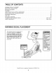
TABLE OF CONTENTS WARNING DECAL PLACEMENT .............................................................. IMPORTANT PRECAUTIONS ................................................................ BEFORE YOU BEGIN ...................................................................... ASSEMBLY ............................................................................... HOW TO USE THE ELLIPTICAL EXERCISER .................................................. MAINTENANCE AND TROUBLESHOOTING ........................
IMPORTANT PRECAUTIONS 3
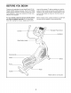
BEFORE YOU BEGIN Thank you for selecting the new NordicTrack ® E7 SV FRONT DRIVE elliptical exerciser. The E7 SV FRONT DRIVE elliptical exerciser provides a wide array of features designed to make your workouts at home more effective and enjoyable. cover of this manual. To help us assist you, note the product model number and serial number before contacting us. The model number and the location of the serial number decal are shown on the front cover of this manual.
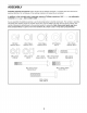
ASSEMBLY Assembly requires two persons. Place all parts of the elliptical exerciser in a cleared area and remove the packing materials. Do not dispose of the packing materials until assembly is completed. In addition to the included tool(s), assembly requires a Phillips screwdriver _====_, wrenches _, two adjustable and a rubber mallet _. As you assemble the elliptical exerciser, use the drawings below to identify small parts.
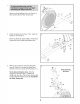
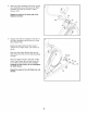
. Attach the Front Stabilizer (6) to the Frame (1) with two M8 x 80mm Patch Screws (84). . 84 Orient the Ramp (3) as shown. Then, insert the Ramp into the Frame (1). Attach the Ramp (3) with five M8 x 19mm Patch Screws (82) and five M8 Split Washers (83). 82 82 . While a second person holds the Upright (4) near the Frame (1), connect the Upper Wire Harness (110) to the Lower Wire Harness (111). Avoid pinching the wires Tip: Avoid pinching the wires. Slide the Upright (4) onto the Frame (1).
Apply a small amount of the included grease to the right Crank Arm (20) and to a 19mm Wave Washer (66). Grease Slide a Crank Arm Spacer (55) and the 19mm Wave Washer (66) onto the right Crank Arm (20). 98 Identify the Right Roller Arm (59), which is marked with a "Right" sticker, and orient it as shown. 53 59 Slide the Right Roller Arm (59) onto the right Crank Arm (20).
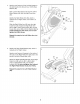
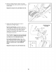
6. Identify the Right Handlebar (61) and the Right Handlebar Leg (60), which are marked with "Right" stickers, and orient them as shown. Make sure that the hexagonal holes are in the indicated location. 6 61 Slide the Right Handlebar (61) onto the Right Handlebar Leg (60). 102 Attach the Right Handlebar (61) with two M8 x 38mm Bolts (96) and two M8 Locknuts (102). Make sure that the Locknuts are in the hexagonal Hexagonal Holes holes.
8. Attach an Outer Handlebar Cover (67) and the Inner Handlebar Cover (68) around the Right Handlebar Leg (60) with two M4 x 16mm Screws (104). 8 Repeat this step for the other side of the elliptical exerciser. 60 67 68 . Apply a small amount of grease to the axle on the Right Handlebar Leg (60) and to a 19mm Wave Washer (66). Identify the Right Pedal Arm (58), which is marked with a "Right" sticker, and orient it as shown.
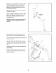
. Attach the Right Pedal Arm (58) to the Right Pedal Bracket (64) with two M10 x 45mm Patch Screws (99). 10 44 Repeat this step for the Left Pedal Arm (44). 58 11. Identify the Right Pulse Bar (9), which is marked with a "Right" sticker. 11 Avoid pinching the wires See the inset drawing. Locate the wire tie in the Upright (4). Tie the lower end of the wire tie to the Pulse Wire (63) in the Right Pulse Bar (9). Next, pull the upper end of the wire tie upward out of the top of the Upright.
12.AttachtheWaterBottleHolder(37)to the Upright(4)withtwoM4x 16mmScrews(104). 12 13.Whilea secondpersonholdstheConsole(7) neartheUpright(4),connecttheconsolewire tothe UpperWireHarness(110).Then,connect theconsolepulsewirestothe PulseWires(63). 13 Avoid pinching the wires Console Wire Insert the excess wire downward into the Upright (4). 110 Tip: Avoid pinching the wires. Attach the Console (7) to the Upright (4) with four M4 x 16mm Screws (104). See step 3. Tighten the M8 x 19mm Patch Screws (82).
HOW TO USE THE ELLIPTICAL EXERCISER HOW TO PLUG IN THE POWER ADAPTER HOW TO MOVE THE ELLIPTICAL Plug one end of the included power adapter into the jack on the console. Plug the other end of the power adapter into an appropriate outlet that is properly installed in accordance with all local codes and ordinances. Due to the size and weight of the elliptical exerciser, moving it requires two persons.
HOW TO EXERCISE ON THE ELLIPTICAL EXERCISER HOW TO CHANGE THE INCLINE OF THE RAMP To vary the motion of the pedals, you can change the incline of the ramp. To change the incline, press the latch button, pull the ramp handle, and raise or lower the ramp to the desired incline level. Then, release the latch button and engage the latch pin into one of the adjustment holes in the frame. The white line on the latch button must be visible or the latch pin is not fully engaged.
CONSOLE DIAGRAM WEIGHT B l"!,e'! U'U B ENDURANCE TIME RESEF 2.64 ,5u DISTANCE ODOMETER WEIGHT 2 LOSS LOSS 3 SPEED WEIGIII PERFORMANCE LOSS 4 / / \ ?fit d fit TRAINER WEIGHT LOSS WORKOUTS WORKOUTS WORKOUTS a[ iFIT.COM \ SILENT MAGNETIC \ \ \ \ \ RESISTANCE / / A V J FEATURES OF THE CONSOLE / out. iFit workouts control the resistance of the pedals while the voice of a personal trainer coaches you through your workouts, iFit cards are available separately.
HOW TO USE THE MANUAL MODE 1. The lower right display--The lower right display can show the your pedaling speed (in miles or kilometers Begin pedaling or press any button on the console to turn on the console. A moment after you begin pedaling or press a button, a tone will sound, and the display will light. 2. be selected. If you have selected a workout, reselect the manual mode theupper I ¸ F'I F'I,F'I t"ll display--The UU'UU Fll-1 U.U DISTANCE tons repeatedly until zeros appear in the display.
5. Measure your heart rate if desired. If there are sheets If the display does not show your heart rate, make sure that your hands are positioned as described. Be careful not to move your hands excessively or to squeeze the metal contacts tightly. For optimal performance, clean the metal contacts using a soft cloth; never use alcohol, abrasives, or chemicals to clean the contacts. I of clear plastic on I Contacts the metal contacts on the handgrip pulse sensor, remove the plastic.
HOW TO USE A TRAINER WORKOUT 1. ment of the workout. The height of the flashing segment indicates the resistance level for the current segment. At the end of each segment of the workout, a series of tones will sound and the next segment of the profile will begin to flash. If a different resistance level is programmed for the next segment, the resistance level will appear in the display for a few seconds to alert you. The resistance of the pedals will then change.
HOW TO USE A WEIGHT LOSS WORKOUT 1. rent segment. At the end of each segment of the workout, a series of tones will sound and the next segment of the profile will begin to flash. If a different resistance level is programmed for the next segment, the resistance level will appear in the display for a few seconds to alert you. The resistance of the pedals will then change. Begin pedaling or press any button on the console to turn on the console.
HOW TO USE AN IFIT WORKOUT HOW TO USE THE SOUND SYSTEM 1. To play music or audio books through the console's sound system while you exercise, plug an audio cable (not included) into the jack on the console and into a jack on your MP3 player or CD player; make sure that the audio cable is fully plugged in. Begin pedaling or press any button on the console to turn on the console. A moment after you begin pedaling or press a button, a tone will sound, and the display will light. 2.
HOW TO CHANGE CONSOLE SETTINGS 3. The console features a user mode that allows you to select a unit of measurement and a backlight option for the console and to view console usage information. 1. The lower right display will show the selected unit of measurement. An E for English miles or an M for metric kilometers will appear in the lower right display. To change the unit of measurement, press the Silent Magnetic Resistance decrease button repeatedly. Select the user mode.
MAINTENANCE AND TROUBLESHOOTING HOW TO ADJUST THE REED SWITCH Inspect and tighten all parts of the elliptical exerciser regularly. Replace any worn parts immediately. If the console does not display correct feedback, the reed switch should be adjusted. To adjust the reed switch, first use a flat screwdriver to pry the left disc carefully away from the left disc mount. Then, remove the left disc. To clean the elliptical exerciser, use a damp cloth and a small amount of mild soap.
EXERCISE GUIDELINES Burning Fat--To burn fat effectively, you must exercise at a low intensity level for a sustained period of time. During the first few minutes of exercise, your body uses carbohydrate calories for energy. Only after the first few minutes of exercise does your body begin to use stored fat calories for energy. If your goal is to burn fat, adjust the intensity of your exercise until your heart rate is near the lowest number in your training zone.
PART LIST--Model Key No. Qty. 1 2 1 1 3 4 5 6 7 8 No. NTEL07808.0 Description Rloo8A Key No. Qty.
Key No. Qty. 101 102 103 104 105 106 107 108 109 2 12 1 17 10 1 4 12 2 Description M8 x 20mm Washer M8 Locknut M3.5 x 12mm Flat Head Screw M4 x 16mm Screw M4 x 10mm Machine Screw M4 x 16mm Bright Screw Roller Arm Bushing M6 x 13mm Screw M6 Washer Key No. Qty. 110 111 112 113 114 * * * * 1 1 1 1 2 - Description Upper Wire Harness Lower Wire Harness Power Adapter Drive Belt Foam Grip 1" Grommet Assembly Tool Grease Packet User's Manual Note: Specifications are subject to change without notice.
EXPLODED DRAWING A--Model 81 No. NTEL07808.0 moo8A 34 84 69 78 38 J 86 20 "" 104 43 34 35 81 36 18 82 20 83 85 83 109 108 86 102 11 4 15 82 ....-13 91 29 32 .
EXPLODED DRAWING B--Model No. NTEL07808.
EXPLODED DRAWING C--Model No. NTEL07808.
ORDERING REPLACEMENT PARTS To order replacement parts, please see the front cover of this manual.