Model No. NCTL09707.0 Serial No. Write the serial number in the space above for reference. USER'S MANUAL Serial Number Decal QUESTIONS? As a manufacturer, we are committed to providing complete customer satisfaction. If you have questions, or if parts are missing, PLEASE DO NOT CONTACT THE STORE; please contact Customer Care. IMPORTANT: You must note the product model number and serial number (see the drawing above) before contacting us: 1-888-936-4266 CALL TOLL-FREE: Mon.–Fri.
TABLE OF CONTENTS WARNING DECAL PLACEMENT . . . . . . . . . . . . . . . . . . . . . . . . . . . . . . . . . . . . . . . . . . . . . . . . . . . . . . . . . . . . . .2 IMPORTANT PRECAUTIONS . . . . . . . . . . . . . . . . . . . . . . . . . . . . . . . . . . . . . . . . . . . . . . . . . . . . . . . . . . . . . . . . .3 BEFORE YOU BEGIN . . . . . . . . . . . . . . . . . . . . . . . . . . . . . . . . . . . . . . . . . . . . . . . . . . . . . . . . . . . . . . . . . . . . . . .5 ASSEMBLY . . . . . . . . . . .
IMPORTANT PRECAUTIONS WARNING: To reduce the risk of serious injury, read all important precautions and instructions in this manual and all warnings on your treadmill before using your treadmill. ICON assumes no responsibility for personal injury or property damage sustained by or through the use of this product. 1. Before beginning any exercise program, consult your physician. This is especially important for persons over the age of 35 or persons with pre-existing health problems.
24. Inspect and properly tighten all parts of the treadmill regularly. 20. Never leave the treadmill unattended while it is running. Always remove the key, unplug the power cord, and switch the reset/off circuit breaker to the off position when the treadmill is not in use. (See the drawing on page 5 for the location of the circuit breaker.) 25. 21. Do not attempt to raise, lower, or move the treadmill until it is properly assembled.
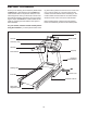
BEFORE YOU BEGIN Thank you for selecting the revolutionary NordicTrack® COMMERCIAL 1500 treadmill. The COMMERCIAL 1500 treadmill offers an impressive selection of features designed to make your workouts at home more enjoyable and effective. And when youʼre not exercising, the unique COMMERCIAL 1500 treadmill can be folded up, requiring less than half the floor space of other treadmills. ing this manual, please see the front cover of this manual.
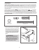
ASSEMBLY Assembly requires two persons. Set the treadmill in a cleared area and remove all packing materials. Do not dispose of the packing materials until assembly is completed. Note: The underside of the treadmill walking belt is coated with high-performance lubricant. During shipping, a small amount of lubricant may be transferred to the top of the walking belt or the shipping carton. This is a normal condition and does not affect treadmill performance.
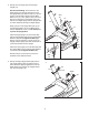
2. Identify the Left Upright (73) and the Right Upright (74). 2 See the inset drawing. Tie the wire tie in the Right Upright (74) securely around the end of the Upright Wire (75). With the help of a second person, hold the Right Upright near the Right Base Cover (77). Then, pull the other end of the Wire tie up through the rectangular hole in the bottom of the Right Upright until the Upright Wire is routed completely through the Right Upright.
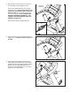
4. With the help of a second person, hold the console assembly near the Uprights (73, 74). 4 Connect the Upright Wire (75) to the Console Wire Harness (71). See the inset drawing. The connectors should slide together easily and snap into place. If they do not, turn one connector and try again. IF THE CONNECTORS ARE NOT CONNECTED PROPERLY, THE CONSOLE MAY BE DAMAGED WHEN THE POWER IS TURNED ON. Console Assembly 73 Remove the tie from the Upright Wire (75). 75 5.
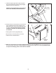
7. Slide the Right Upright Sleeve (96) up against the console assembly. Attach the Right Upright Sleeve with two 3/4" Screws (4). 7 Console Assembly Attach the Left Upright Sleeve (not shown) to the console assembly as described above. 96 4 4 8. With the help of a second person, raise the front of the treadmill and insert the crossbar on the Base (83) into the cutout in the cardboard stand as shown. Have the second person hold the treadmill to prevent it from moving forward or backward.
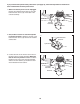
If you purchase the optional chest pulse sensor (see page 19), follow the steps below to install the receiver included with the chest pulse sensor. 1. Make sure that the power cord is unplugged. Remove the indicated 3/4" Screws (4) from the Pulse Receiver Cover (70) on the back of the console assembly. 1 Console Assembly 70 4 2. Next, hold the receiver so the small cylinder is oriented as shown. Attach the receiver to the Pulse Receiver Cover (70) with the two included small screws. 3.
OPERATION AND ADJUSTMENT THE PRE-LUBRICATED WALKING BELT an equipment-grounding conductor and a grounding plug. Plug the power cord into a surge suppressor, and plug the surge suppressor into an appropriate outlet that is properly installed and grounded in accordance with all local codes and ordinances. Important: The treadmill is not compatible with GFCI-equipped outlets. Your treadmill features a walking belt coated with highperformance lubricant.
CONSOLE DIAGRAM Key Clip FEATURES OF THE CONSOLE To turn on the power, see page 13. To personalize console settings, see page 13. To use the manual mode, see page 14. To use a preset workout, see page 16. To create and use a custom workout, see pages 17 and 18. To use the sound system, see page 19. The treadmill console offers an impressive array of features designed to make your workouts more effective and enjoyable.
HOW TO TURN ON THE POWER IMPORTANT: If the treadmill has been exposed to cold temperatures, allow it to warm to room temperature before turning on the power. If you do not do this, the console display or other electrical components may become damaged. Plug in the power cord (see page 11). Next, locate the reset/off circuit breaker on the treadmill frame near the power cord. Make sure that the circuit breaker is in the “reset” position.
HOW TO USE THE MANUAL MODE the incline buttons numbered 0 to 12. Each time you press one of the buttons, the incline will gradually change until it reaches the selected incline setting. 1. Insert the key into the console. See HOW TO TURN ON THE POWER on page 13. 2. Personalize console settings if desired. See HOW TO PERSONALIZE CONSOLE SETTINGS on page 13. 6. Select a display mode and monitor your progress with the display and the intensity level bar.
Regardless of which display mode you select, the speed or incline setting will appear in the display for a few seconds each time you change the setting. In addition, your heart rate will appear in the display each time you use the handgrip pulse sensor or put on the optional chest pulse sensor. Note: If you select the display mode shown above, your heart rate will be shown in place of the approximate exercise pace.
HOW TO USE A PRESET WORKOUT At the end of the first one-minute segment of the workout, a series of tones will sound. If a different speed and/or incline setting is programmed for the second segment, the speed setting and/or incline setting will appear in the display for a moment to alert you. The treadmill will then automatically adjust to the speed and incline settings for the second segment. 1. Insert the key into the console. See HOW TO TURN ON THE POWER on page 13. 2.
HOW TO CREATE A CUSTOM WORKOUT To program a speed setting and an incline setting for the first one-minute segment of the workout, simply adjust the speed and incline of the treadmill as desired by pressing the Speed and Incline buttons. 1. Insert the key into the console. See HOW TO TURN ON THE POWER on page 13. When the first segment ends, a series of tones will sound and the current speed and incline settings will be saved in memory. 2. Personalize console settings if desired.
HOW TO USE A CUSTOM WORKOUT At the end of the first one-minute segment of the workout, a series of tones will sound. If a different speed and/or incline setting is programmed for the second segment, the speed and/or incline setting will appear in the display for a moment to alert you. The treadmill will then automatically adjust to the speed and incline settings for the second segment. 1. Insert the key into the console. See HOW TO TURN ON THE POWER on page 13. 2.
HOW TO USE THE SOUND SYSTEM To play music or audio books through the consoleʼs speaker, you must connect your MP3 player, CD player, or other personal audio player to the console. Locate the audio wire below the display on the console, and plug it into a jack on your MP3 player, CD player, or other personal audio player. Make sure that the audio/video cable is fully plugged in.
HOW TO FOLD AND MOVE THE TREADMILL HOW TO FOLD THE TREADMILL FOR STORAGE Before folding the treadmill, adjust the incline to the lowest position. If you do not do this, you may damage the treadmill when you fold it. Remove the key and unplug the power cord. CAUTION: You must be able to safely lift 45 lbs. (20 kg) to raise, lower, or move the treadmill. 1. Hold the metal frame firmly in the location shown by the arrow at the right.
HOW TO LOWER THE TREADMILL FOR USE Frame 1. Hold the upper end of the treadmill with your right hand. Pull the latch knob to the left and hold it. It may be necessary to push the frame forward as you pull the knob to the left. Pivot the frame downward and release the latch knob. Latch Knob 2. Hold the metal frame firmly with both hands, and lower it to the floor. CAUTION: To decrease the possibility of injury, do not lower the frame by gripping only the plastic foot rails.
TROUBLESHOOTING Most treadmill problems can be solved by following the steps below. Find the symptom that applies, and follow the steps listed. If further assistance is needed, please see the front cover of this manual. PROBLEM: The power does not turn on SOLUTION: a. Make sure that the power cord is plugged into a surge suppressor, and that the surge suppressor is plugged into a properly grounded outlet (see page 11).
Lower the treadmill (see HOW TO LOWER THE TREADMILL FOR USE on page 21). Remove the four indicated 3/4" Screws (4), and remove the Hood (44). 4 4 44 Next, locate the Reed Switch (20) and the Magnet (12) on the left side of the Pulley (11). Turn the Pulley until the Magnet is aligned with the Reed Switch. Make sure that the gap between the Magnet and the Reed Switch is about 1/8 in. (3 mm). If necessary, loosen the indicated 3/4" Tek Screw (29), move the Reed Switch slightly, and then retighten the Screw.
PROBLEM: The walking belt is off-center or slips when walked on SOLUTION: a. If the walking belt is off-center, remove the key and UNPLUG THE POWER CORD. If the walking belt has shifted to the left, use the hex key to turn the left rear roller bolt clockwise 1/2 of a turn; if the walking belt has shifted to the right, turn the left rear roller bolt counterclockwise 1/2 of a turn. Be careful not to overtighten the walking belt. Plug in the power cord, insert the key, and run the treadmill for a few minutes.
EXERCISE GUIDELINES WARNING: Before beginning any exercise program, consult your physician. This is especially important for persons over the age of 35 or persons with pre-existing health problems. The pulse sensor is not a medical device. Various factors may affect the accuracy of heart rate readings. The pulse sensor is intended only as an exercise aid in determining heart rate trends in general. These guidelines will help you to plan your exercise program.
PART LIST—Model No. NCTL09707.0 To locate the parts listed below, see the EXPLODED DRAWING attached in the center of this manual. Key No. Qty. 1 2 3 4 5 6 7 8 9 10 11 12 13 14 15 16 17 18 19 20 21 22 23 24 25 26 27 28 29 30 31 32 33 34 35 36 37 38 39 40 41 42 43 44 45 46 47 48 49 50 2 2 8 62 4 1 2 4 2 2 1 1 17 1 2 2 2 2 2 1 2 1 1 1 1 1 1 1 9 2 1 2 4 1 1 1 1 10 1 1 1 2 1 1 4 2 1 1 1 1 Description Key No. Qty.
Key No. Qty. 101 102 103 104 105 106 107 108 109 1 1 4 1 2 1 1 1 2 Description Latch Warning Decal French Latch Warning Decal Clamp Screw Speaker Cover Rear Roller Washer Incline/Controller Wire Incline Stop Bracket Stop Bracket Spacer 1/2" Console Ground Screw Key No. Qty. 110 111 112 113 * * 1 8 1 1 – – Description Console Plate #8 x 3/4" Screw Lower Latch Bolt Transformer 8" Blue Wire, 2F Userʼs Manual *These parts are not illustrated. Specifications are subject to change without notice.
2 57 59 38 58 4 105 52 56 3 62 1 29 97 61 101 54 3 56 52 97 105 4 6 42 60 29 3 61 51 38 62 7 8 48 102 3 3 4 47 9 4 4 18 2 10 3 17 28 1 16 30 42 69 11 12 20 14 29 4 19 15 3 113 29 38 10 8 32 31 3 4 7 55 33 33 69 33 22 9 34 55 55 4 4 13 36 69 23 46 15 29 35 4 18 37 38 16 100 17 19 30 13 41 38 98 40 39 43 38 68 107 49 108 25 112 44 24 106 4 45 53 4 4 45 4 EXPLODED DRAWING—Model No. NCTL09707.
94 13 89 13 5 104 13 13 13 79 111 4 80 111 63 94 4 26 21 110 109 13 50 84 5 103 4 4 78 13 66 84 99 4 21 4 4 103 4 70 111 4 27 111 111 4 80 111 13 4 67 71 76 4 92 29 91 86 87 65 4 4 85 4 4 4 4 4 64 95 38 90 93 82 88 81 4 4 90 4 4 38 64 90 73 86 90 38 72 82 4 88 81 4 90 85 83 64 96 69 75 88 82 81 4 64 4 46 87 90 75 4 87 90 38 72 74 77 82 88 81 EXPLODED DRAWING—Model No. NCTL09707.
ORDERING REPLACEMENT PARTS To order replacement parts, please see the front cover of this manual.