www.nordictrack.com Model No. NTL19010.2 Serial No. Write the serial number in the space above for reference. Serial Number Decal QUESTIONS? If you have questions, or if parts are damaged or missing, DO NOT CONTACT THE STORE; please contact Customer Care. IMPORTANT: Please register this product (see the limited warranty on the back cover of this manual) before contacting Customer Care. CALL TOLL-FREE: 1-800-TO-BE-FIT (1-800-862-3348) Mon.–Fri. 6 a.m.–6 p.m. MT Sat. 8 a.m.–4 p.m. MT ON THE WEB: www.
TABLE OF CONTENTS WARNING DECAL PLACEMENT . . . . . . . . . . . . . . . . . . . . . . . . . . . . . . . . . . . . . . . . . . . . . . . . . . . . . . . . . . . . . . 2 IMPORTANT PRECAUTIONS. . . . . . . . . . . . . . . . . . . . . . . . . . . . . . . . . . . . . . . . . . . . . . . . . . . . . . . . . . . . . . . . . 3 BEFORE YOU BEGIN. . . . . . . . . . . . . . . . . . . . . . . . . . . . . . . . . . . . . . . . . . . . . . . . . . . . . . . . . . . . . . . . . . . . . . . 5 PART IDENTIFICATION CHART. . .
IMPORTANT PRECAUTIONS WARNING: To reduce the risk of serious injury, read all important precautions and instructions in this manual and all warnings on your incline trainer before using your incline trainer. ICON assumes no responsibility for personal injury or property damage sustained by or through the use of this product. 1. Before beginning any exercise program, consult your physician. This is especially important for persons over age 35 or persons with pre-existing health problems. 11.
19. The heart rate monitor is not a medical device. Various factors, including the user’s movement, may affect the accuracy of heart rate readings. The heart rate monitor is intended only as an exercise aid in determining heart rate trends in general. 23. Inspect and properly tighten all parts of the incline trainer regularly. DANGER: 24.
BEFORE YOU BEGIN Thank you for selecting the revolutionary NORDICTRACK® INCLINE TRAINER X9i INTERACTIVE. The INCLINE TRAINER X9i INTERACTIVE offers a selection of features designed to make your workouts at home more enjoyable and effective. reading this manual, please see the front cover of this manual. To help us assist you, note the product model number and serial number before contacting us. The model number and the location of the serial number decal are shown on the front cover of this manual.
PART IDENTIFICATION CHART Use the drawings below to identify small parts used for assembly. The number in parentheses below each drawing is the key number of the part, from the PART LIST near the end of this manual. The number following the key number is the quantity used for assembly. Note: If a part is not in the hardware kit, check to see if it is preattached. Extra hardware may be included.
ASSEMBLY • Assembly requires two persons. • To identify small parts, see page 6. • P lace all parts in a cleared area and remove the packing materials. Do not dispose of the packing materials until you finish all assembly steps. • Assembly requires the following tools: the included hex keys one Phillips screwdriver • T he underside of the walking belt is coated with high-performance lubricant.
2. Attach the Upright (77) to the Base (80) with two 3/8" x 5 1/2" Screws (5) and a 3/8" x 2 3/4" Screw (17) with three 3/8" Star Washers (8) as shown. Start all three Screws, and then tighten them. Be careful not to pinch the Upright Wire (not shown) in the Upright. 2 77 Attach the other Upright (not shown) as described above. Note: There is not a wire on the left side. 5 8 8 17 80 3. Set the Console (37) face down on a soft surface to avoid scraching the Console.
4. Have a second person hold the console assembly near the Uprights (77). Insert the console wire and the “R” pulse wire from the console assembly through the indicated tie. 4 Tie Connect the Upright Wire (78) to the console wire. See the inset drawing. The connectors should slide together easily and snap into place. If they do not, turn one connector and try again. IF YOU DO NOT CONNECT THE CONNECTORS PROPERLY, THE CONSOLE MAY BECOME DAMAGED WHEN YOU TURN ON THE POWER.
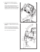
6. Tighten two #8 x 3/4" Screws (1) into the Console Base (87). Do not overtighten the Screws. 6 Identify the Right Handrail Assembly (93). Hold the Right Handrail Assembly near the right Upright (77). Insert the pulse wire from the Right Handrail Assembly into the hole in the top of the Upright and pull it out of the end of the Upright. 1 Pulse Wire 93 1 87 77 7. Set the Right Handrail Assembly (93) onto the right Upright (77). Make sure that no wires are pinched.
8. Hold the Left Handrail Assembly (86) near the left Upright (77). Insert the pulse wire from the left handrail assembly into the hole in the top of the Upright and pull it out of the end of the Upright. 8 86 Set the Left Handrail Assembly (86) onto the left Upright (77). Make sure that no wires are pinched. Attach the Left Handrail Assembly (86) with two 3/8" x 5 1/2" Screws (5) and two 3/8" Star Washers (8). Note: Start the lower Screw first.
10. See page 14 and plug in the power cord. Next, see page 16 and turn on the power. Then, touch the 1 Step Incline button numbered 40 on the console. The Frame (58) will adjust to an incline of 40 percent. Then, turn off the incline trainer and unplug the power cord. 10 58 Identify the Left Inside Cover (3) and the Left Outside Cover (106). Next, hold the Left Inside Cover against the left Upright (77). Then, hold the Left Ouside Cover against the Left Inside Cover.
THE CHEST HEART RATE MONITOR HOW TO PUT ON THE HEART RATE MONITOR The heart rate monitor consists of a chest strap and a sensor. Insert the tab on one end of the chest strap into the hole in one end of the sensor as shown. Then, press the end of the sensor under the buckle on the chest strap. The tab should be flush with the front of the sensor.
OPERATION AND ADJUSTMENT HOW TO CONNECT THE POWER CORD nominal 120-volt circuit capable of carrying 15 or more amps. To avoid overloading the circuit, do not plug other electrical devices, except for lowpower devices such as cell phone chargers, into the surge suppressor or into an outlet on the same circuit. IMPORTANT: The treadmill is not compatible with GFCI-equipped outlets and may not be compatible with AFCI-equipped outlets.
CONSOLE DIAGRAM FEATURES OF THE CONSOLE The incline trainer console offers an impressive array of features designed to make your workouts more effective and enjoyable. The console features revolutionary iFit Live technology that enables the incline trainer to communicate with your wireless network. With iFit Live technology, you can download personalized workouts, create your own workouts, track your workout results, and access many other features. See www.iFit.com for complete information.
HOW TO TURN ON THE POWER HOW TO USE THE TOUCH SCREEN IMPORTANT: If the incline trainer has been exposed to cold temperatures, allow it to warm to room temperature before you turn on the power. If you do not do this, you may damage the console display or other electrical components. The console features a tablet with a full-color touch screen. The following information will help you become familiar with the tablet’s advanced technology: lug in the power cord (see P page 14).
HOW TO SET UP THE CONSOLE Next, enter a username and password and your e-mail address. Enter the activation code from the iFit Live flier that came with the incline trainer. Touch the Place of Purchase drop-down menu for a list of options; then, touch the location where you purchased your product. Touch the words MEDICAL DISCLAIMER, read the medical disclaimer, touch the I Accept button, and check the medical disclaimer checkbox. Then, touch the Confirm Activation Code button.
HOW TO USE THE MANUAL MODE Note: The first time you adjust the incline, you must first calibrate the incline system (see step 4 on page 24). 1. Insert the key into the console. See HOW TO TURN ON THE POWER on page 16. Note: It may take a minute for the console to be ready for use. 5. Monitor your progress. The console offers several display modes. The display mode that you select will determine which workout information is shown.
rate will be shown. For the most accurate heart rate reading, continue to hold the contacts for about 15 seconds. The displays at the top of the screen can show two types of information. Touch each display until the display shows the desired information. If desired, adjust the volume by pressing the volume increase and decrease buttons on the console. 7. Turn on the fan if desired. Decrease The fan features several speed settings and an auto mode.
HOW TO USE AN ONBOARD WORKOUT 1. Insert the key into the console. See HOW TO TURN ON THE POWER on page 16. 2. Select an onboard workout. To select an onboard workout, press the Calorie button, the Intensity button, or the Incline button on the console. Note: You can also touch the runner icon on the screen to select the Workouts menu. Then, select the desired workout. The screen will show the name, duration, and distance of the workout.
HOW TO USE A SET-A-GOAL WORKOUT The workout will function in the same way as the manual mode (see pages 18 and 19). 1. Insert the key into the console. The workout will continue until you reach the goal that you set. The walking belt will then slow to a stop, and a workout summary will appear on the screen. After you view the workout summary, touch the Finish button to return to the main menu. You may also be able to either save or publish your results using one of the options on the screen.
HOW TO USE AN IFIT LIVE WORKOUT Note: To use an iFit Live workout, you must have access to a wireless network (see HOW TO USE THE WIRELESS NETWORK MODE on page 25). An iFit Live account is also required. Before some workouts will download, you must add them to your schedule on iFit.com. For more information about the iFit Live workouts, please see www.iFit.com. 2. Select the main menu. When you select an iFit Live workout, the screen will show the name, duration, and distance of the workout.
HOW TO USE THE EQUIPMENT SETTINGS MODE The console features an equipment settings mode that allows you to select a language and the unit of measurement, to turn on and turn off the display demo mode, and to enable or disable the key. 1. Select the settings main menu. Insert the key into the console (see HOW TO TURN ON THE POWER on page 16). Next, select the main menu (see step 2 on page 18). Then, touch the gears button near the lower right corner of the screen to select the settings main menu. 2.
HOW TO USE THE MAINTENANCE MODE USB drive. Safely remove the USB drive from your computer and plug it into the USB port on the side of the console. The update should begin automatically. The console features a maintenance mode that allows you to update the console firmware, calibrate the incline of the incline trainer, calibrate the screen, view technical information, and view a button’s keycode. The screen will show the progress of the update.
HOW TO USE THE WIRELESS NETWORK MODE An information box will ask if you want to connect to the wireless network. Touch the Connect button to connect to the network or touch the Cancel button to return to the list of networks. If the network has a password, touch the password entry box. A keyboard will appear on the screen. To view the password as you type it, touch the Show Password checkbox. The console features a wireless network mode that allows you to set up a wireless network connection. 1.
HOW TO USE THE STEREO SOUND SYSTEM HOW TO USE THE INTERNET BROWSER To play music or audio books through the console’s speakers, you must connect your MP3 player, CD player, or other personal audio player to the console. Note: To use the browser, you must have access to a wireless network including an 802.11b/n router with SSID broadcast enabled (hidden networks are not supported). Plug one end of your audio wire into the audio jack on the side of the console.
HOW TO MOVE THE INCLINE TRAINER Before moving the incline trainer, insert the key into the console, raise the incline to the maximum incline level, remove the key, and unplug the power cord. Due to the size and weight of the incline trainer, moving it requires two or three persons. Hold the uprights firmly near the console. Tip the incline trainer back until it rolls freely on the wheels.
TROUBLESHOOTING Most incline trainer problems can be solved by following the simple steps below. Find the symptom that applies, and follow the steps listed. If further assistance is needed, see the front cover of this manual. c. Remove the key from the console, and then reinsert it. SYMPTOM: The power does not turn on SYMPTOM: The console displays remain lit when you remove the key from the console d. If the incline trainer still will not run, please see the front cover of this manual. a.
ocate the Reed Switch (55) and the Magnet (41) L on the left side of the Pulley (42). Turn the Pulley until the Magnet is aligned with the Reed Switch. Make sure that the gap between the Magnet and the Reed Switch is about 1/8 in. (3 mm). If necessary, loosen the #8 x 3/4" Clamp Screw (20), move the Reed Switch slightly, and then retighten the Screw. Reattach the Left Roller Cover (not shown) and run the incline trainer for a few minutes to check for a correct speed reading. b.
SYMPTOM: The walking belt is off-center or slips when walked on SYMPTOM: The iFit Live mode does not function correctly a. I f the walking belt is off-center, first adjust the incline to 40 percent. Remove the key and UNPLUG THE POWER CORD. If the walking belt has shifted to the left, use the hex key to turn the left idler roller screw clockwise 1/2 of a turn; if the walking belt has shifted to the right, turn the left idler roller screw counterclockwise 1/2 of a turn.
EXERCISE GUIDELINES Burning Fat—To burn fat effectively, you must exercise at a low intensity level for a sustained period of time. During the first few minutes of exercise, your body uses carbohydrate calories for energy. Only after the first few minutes of exercise does your body begin to use stored fat calories for energy. If your goal is to burn fat, adjust the intensity of your exercise until your heart rate is near the lowest number in your training zone.
SUGGESTED STRETCHES The correct form for several basic stretches is shown at the right. Move slowly as you stretch—never bounce. 1. Toe Touch Stretch Stand with your knees bent slightly and slowly bend forward from your hips. Allow your back and shoulders to relax as you reach down toward your toes as far as possible. Hold for 15 counts, then relax. Repeat 3 times. Stretches: Hamstrings, back of knees and back. 1 2. Hamstring Stretch Sit with one leg extended.
PART LIST Key No. Qty.
Key No. Qty. Description Key No. Qty. Description 101 102 103 104 105 106 Console Crossbar #8 x 1" Screw Crossbar Console Clamp 3/8" x 2 1/2" Screw Left Outside Cover 107 108 109 110 * Frame Bushing Computer 1/4" Nut Leveling Feet User’s Manual 1 4 1 2 2 1 2 1 1 4 – Note: Specifications are subject to change without notice. For information about ordering replacement parts, see the back cover of this manual. *These parts are not illustrated.
35 42 28 40 38 41 1 23 36 14 35 1 36 35 15 39 68 28 62 23 35 72 1 1 35 44 1 1 28 18 21 43 45 18 28 1 85 1 1 35 18 1 35 54 1 35 1 35 1 28 35 35 35 18 28 23 35 85 35 1 1 35 1 47 28 18 25 1 35 66 48 1 53 52 21 23 1 81 1 28 13 1 43 1 51 25 1 50 1 EXPLODED DRAWING A Model No. NTL19010.
71 1 36 75 22 55 31 70 13 56 33 20 61 107 7 26 30 13 13 30 13 30 13 69 13 1 22 109 31 29 49 26 32 33 7 1 107 46 60 73 79 74 73 46 1 26 58 1 65 32 73 79 74 73 46 1 64 46 13 59 26 7 33 26 63 13 33 26 7 13 EXPLODED DRAWING B Model No. NTL19010.
84 57 37 110 24 83 82 1 106 84 80 24 1 110 36 3 81 17 110 8 82 57 2 78 10 81 110 1 1 36 2 10 94 8 17 92 EXPLODED DRAWING C Model No. NTL19010.
EXPLODED DRAWING D Model No. NTL19010.
EXPLODED DRAWING E Model No. NTL19010.
ORDERING REPLACEMENT PARTS To order replacement parts, please see the front cover of this manual.