www.nordictrack.com Model No. 831.24988.1 Serial No. Write the serial number in the space above for reference. Serial Number Decal ACTIVATE YOUR WARRANTY To register your product and activate your warranty today, go to www.nordictrackservice.com/ registration. CUSTOMER CARE For service at any time, go to www.nordictrackservice.com. Or call 1-800-TO-BE-FIT (1-800-862-3348) Mon.–Fri. 6 a.m.–6 p.m. MT Sat. 8 a.m.–4 p.m. MT Please do not contact the store.
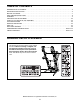
TABLE OF CONTENTS WARNING DECAL PLACEMENT . . . . . . . . . . . . . . . . . . . . . . . . . . . . . . . . . . . . . . . . . . . . . . . . . . . . . . . . . . . . . . .2 IMPORTANT PRECAUTIONS. . . . . . . . . . . . . . . . . . . . . . . . . . . . . . . . . . . . . . . . . . . . . . . . . . . . . . . . . . . . . . . . . . 3 BEFORE YOU BEGIN. . . . . . . . . . . . . . . . . . . . . . . . . . . . . . . . . . . . . . . . . . . . . . . . . . . . . . . . . . . . . . . . . . . . . . . .7 PART IDENTIFICATION CHART.
IMPORTANT PRECAUTIONS WARNING: To reduce the risk of burns, fire, electric shock, or injury to persons, read all important precautions and instructions in this manual and all warnings on your treadmill before using your treadmill. ICON assumes no responsibility for personal injury or property damage sustained by or through the use of this product. 1. It is the responsibility of the owner to ensure that all users of this treadmill are adequately informed of all warnings and precautions. 12.
24. Never insert any object into any opening on the treadmill. 20. The heart rate monitor is not a medical device. Various factors, including the user’s movement, may affect the accuracy of heart rate readings. The heart rate monitor is intended only as an exercise aid in determining heart rate trends in general. 25. Inspect and properly tighten all parts of the treadmill regularly. 26. 21. Never leave the treadmill unattended while it is running.
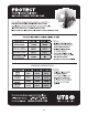
STANDARD SERVICE PLANS all 6
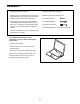
BEFORE YOU BEGIN Thank you for selecting the revolutionary NORDICTRACK® C 700 treadmill. The C 700 treadmill offers an impressive selection of features designed to make your workouts at home more effective and enjoyable. And when you’re not exercising, the unique treadmill can be folded up, requiring less than half the floor space of other treadmills. reading this manual, please see the front cover of this manual.
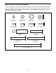
PART IDENTIFICATION CHART Use the drawings below to identify small parts used for assembly. The number in parentheses below each drawing is the key number of the part, from the PART LIST near the end of this manual. The number following the key number is the quantity used for assembly. Note: If a part is not in the hardware kit, check to see if it is preattached. Extra parts may be included.
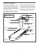
ASSEMBLY • Assembly requires two persons. • To identify small parts, see page 8. • Place all parts in a cleared area and remove the packing materials. Do not dispose of the packing materials until you finish all assembly steps. • Assembly requires the following tools: the included hex key one adjustable wrench • After shipping, there may be an oily substance on the exterior of the treadmill. This is normal.
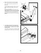
2. Make sure that the power cord is unplugged. 2 Press a Base Cap (74) into each side of the Base (94). Wire 81 Tie 81 Identify the Right Upright (90). Have a second person hold the Right Upright near the Base (94). 90 See the inset drawing. Tie the wire tie in the Right Upright (90) securely around the end of the Upright Wire (81). Then, insert the Upright Wire into the lower end of the Right Upright as you pull the other end of the wire tie out of the Right Upright. 74 Wire Tie 90 74 94 3.
4. Insert a Wheel Spacer (63) into a Front Wheel (62). Hold the Front Wheel inside the bottom of the Right Upright (90), and insert a 3/8" x 4" Screw (7) with a 3/8" Star Washer (13) into the Right Upright and the Front Wheel. 4 Repeat this step with the Left Upright (not shown). 90 13 7 5. Place a piece of packing material (A) under the right side of the Base (94). Hold the Right Upright (90) against the Base. Make sure not to pinch the Upright Wire (81).
6. Remove the four indicated 5/16" x 3/4" Screws (4) from the Uprights (89, 90) (only one side is shown). Save the Screws; the Screws will be used in a later step. 6 4 Identify the Left and Right Base Covers (82, 83). Slide the Left Base Cover onto the Left Upright (89), and slide the Right Base Cover onto the Right Upright (90). Do not press the Base Covers into place yet. 89 82 90 83 7. Identify the right handrail assembly (B).
8. Attach the left handrail assembly (D) to the Left Upright (89) with two 5/16" x 2 1/2" Screws (28) and two 5/16" Star Washers (11); do not fully tighten the Screws yet. 8 28 Remove the two indicated screws (C) from the left handrail assembly (D), and discard the screws. 11 C D 89 9. Set the Console Base (64) face down on a soft surface to avoid scratching the Console Base. 9 4 Remove the two indicated screws (E) from the Pulse Crossbar (93), and discard the screws.
10. Identify the Right and Left Trays (27, 36). 10 Attach the Trays (27, 36) to the Console Base (64) with eight #8 x 1/2" Screws (1). Note: It may be easier to start the two inside Screws and then slide the Trays into place before tightening the other six Screws. 18 27 1 1 36 ote: It may be necessary to rotate the N Console Frame (18) upward when attaching the Trays (27, 36). 1 64 1 1 11.
12. With the help of a second person, hold the console assembly near the Handrails (86) (only one side is shown). Connect the ground wire from the console assembly to the Console Ground Wire (58) on the Pulse Crossbar (93). Connect the Upright Wire (81) to the console wire. See the inset drawing. The connectors should slide together easily and snap into place. If they do not, turn one connector and try again.
14. Attach the Pulse Crossbar (93) to the console assembly with six #8 x 3/4" Screws (2). Start all six Screws, and then tighten them. 14 Console Assembly Firmly tighten the four 5/16" x 3/4" Screws (4). 4 4 93 2 15. Check the gaps between the handrail assemblies (B, D) and the console assembly. 2 2 15 Console Assembly If necessary, loosen the four #8 x 3/4" Screws (2) under the handrails and slide the handrails forward against the console assembly. Then, retighten the Screws.
16. Tighten a #8 x 3/4" Screw (2) into the Left Outside Upright Cover (87) and into the bottom of the left handrail assembly (D). Make sure not to overtighten the Screw. 16 Press the Left Inside Upright Cover (88) against the Left Outside Upright Cover (87) until they snap together. D Repeat the steps above on the other side of the treadmill with the Right Inside Upright Cover (95) and the Right Outside Upright Cover (96). 2 87 95 88 96 2 17.
. Firmly tighten the six 3/8" x 4" Screws (7) (only one side is shown). 18 Press the Left Base Cover (82) and the Right Base Cover (83) onto the Base (94). 82 83 7 94 19. Note: If assembled on a smooth surface, the treadmill may roll forward during this step. 19 Raise the Frame (56) to the upright position. Have a second person hold the Frame until step 21 is completed. Brackets Remove the two 5/16" x 3/4" Screws (4) from the Latch Crossbar (38).
20. Orient the Storage Latch (53) so that the decals are facing away from the treadmill as shown. 20 Attach the lower end of the Storage Latch (53) to the bracket on the Base (94) with a 5/16" x 1 3/4" Bolt (6) and a 5/16" Nut (12). F G 56 Raise the Storage Latch (53) to a vertical position. If there is a tie (F) and spacer (G) in the top of the Latch, remove and discard them. Large Barrel 53 Decals 12 21.
OPERATION AND ADJUSTMENT HOW TO CONNECT THE POWER CORD nominal 120-volt circuit capable of carrying 15 or more amps. To avoid overloading the circuit, do not plug other electrical devices, except for lowpower devices such as cell phone chargers, into the surge suppressor or into an outlet on the same circuit. IMPORTANT: The treadmill is not compatible with GFCI-equipped outlets and may not be compatible with AFCI-equipped outlets.
CONSOLE DIAGRAM FEATURES OF THE CONSOLE The treadmill console offers an impressive array of features designed to make your workouts more effective and enjoyable. When you use the manual mode, you can change the speed and incline of the treadmill with the touch of a button. As you exercise, the console will display instant exercise feedback. You can even measure your heart rate using the handgrip heart rate monitor. In addition, the console features a selection of onboard workouts.
HOW TO TURN ON THE POWER HOW TO USE THE MANUAL MODE IMPORTANT: If the treadmill has been exposed to cold temperatures, allow it to warm to room temperature before you turn on the power. If you do not do this, you may damage the console displays or other electrical components. 1. Insert the key into the console. Plug in the power cord (see page 20). Next, locate the power switch on the treadmill frame near the power cord. Press the power switch into the reset position.
4. Change the incline of the treadmill as desired. The My Trail tab will show a track that represents 1/4 mile (400 m). As you exercise, the flashing rectangle will show your progress. The My Trail tab will also show the number of laps you complete. To change the incline of the treadmill, press the Incline increase and decrease buttons or one of the numbered Incline buttons. Each time you press one of the buttons, the treadmill will gradually adjust to the selected incline setting.
6. Measure your heart rate if desired. Before using the handgrip heart rate monitor, remove the sheets of plastic from the metal contacts on the pulse bar. In addition, make sure that your hands are clean. Press the small fan button repeatedly to select a fan speed or to turn off the fan. Press the large Auto fan button to select the auto mode or to turn off the fan. 8. When you are finished exercising, remove the key from the console.
HOW TO USE AN ONBOARD WORKOUT The workout will continue in this way until the last segment of the profile flashes in the display and the last segment ends. The walking belt will then slow to a stop. 1. Insert the key into the console. See HOW TO TURN ON THE POWER on page 22. Note: The calorie goal is an estimate of the number of calories that you will burn during the workout. The actual number of calories that you burn will depend on various factors such as your weight.
HOW TO USE A SET-A-GOAL WORKOUT HOW TO USE AN IFIT WORKOUT 1. Insert the key into the console. Note: To use an iFit workout, you must have an optional iFit module. To purchase an iFit module at any time, go to www.iFit.com or call the telephone number on the front cover of this manual. You must also have access to a computer with a USB port and an internet connection. In addition, you must have access to a wireless network including an 802.
For more information about the iFit workouts, please see www.iFit.com. 7. Measure your heart rate if desired. See step 6 on page 24. When you select an iFit workout, the display will show the name, duration, maximum speed setting, and distance of the workout. The display will also show the approximate number of calories you will burn during the workout and a profile of the speed settings of the workout. 8. Turn on the fan if desired. See step 7 on page 24. 9.
THE INFORMATION MODE AUDIO COACH—To turn on or turn off the audio coach, press the Enter button. The console features an information mode that keeps track of treadmill information and allows you to personalize console settings. If an iFit module is connected, you may also select the following screens: 1. Select the information mode. DEFAULT MENU—The default menu will appear when you insert the key into the console or when you press the Home button.
HOW TO FOLD AND MOVE THE TREADMILL HOW TO FOLD THE TREADMILL HOW TO MOVE THE TREADMILL To avoid damaging the treadmill, adjust the incline to zero before you fold the treadmill. Then, remove the key and unplug the power cord. CAUTION: You must be able to safely lift 45 lbs. (20 kg) to raise, lower, or move the treadmill. Before moving the treadmill, fold it as described at the left. CAUTION: Make sure that the storage latch is locked in the storage position. Moving the treadmill may require two people.
TROUBLESHOOTING Most treadmill problems can be solved by following the simple steps below. Find the symptom that applies, and follow the steps listed. If further assistance is needed, see the front cover of this manual. c. Remove the key from the console, and then reinsert it. d. If the treadmill still will not run, please see the front cover of this manual. SYMPTOM: The power does not turn on SYMPTOM: The console displays remain lit when you remove the key from the console a.
Locate the Reed Switch (52) and the Magnet (50) on the left side of the Pulley (49). Turn the Pulley until the Magnet is aligned with the Reed Switch. Make sure that the gap between the Magnet and the Reed Switch is about 1/8 in. (3 mm). If necessary, loosen the #8 x 3/4" Tek Screw (14), move the Reed Switch slightly, and then retighten the Screw. Reattach the Motor Hood (not shown) with the #8 x 3/4" Screws (not shown) and run the treadmill for a few minutes to check for a correct speed reading.
SYMPTOM: The walking belt is off-center or slips when walked on b. I f the walking belt slips when walked on, first remove the key and UNPLUG THE POWER CORD. Using the hex key, turn both idler roller screws clockwise, 1/4 of a turn. When the walking belt is correctly tightened, you should be able to lift each edge of the walking belt 2 to 3 in. (5 to 7 cm) off the walking platform. Be careful to keep the walking belt centered.
EXERCISE GUIDELINES Burning Fat—To burn fat effectively, you must exercise at a low intensity level for a sustained period of time. During the first few minutes of exercise, your body uses carbohydrate calories for energy. Only after the first few minutes of exercise does your body begin to use stored fat calories for energy. If your goal is to burn fat, adjust the intensity of your exercise until your heart rate is near the lowest number in your training zone.
PART LIST Key No. Qty. 1 2 3 4 5 6 7 8 9 10 11 12 13 14 15 16 17 18 19 20 21 22 23 24 25 26 27 28 29 30 31 32 33 34 35 36 37 38 39 40 41 42 43 44 45 46 47 48 23 28 1 10 4 1 6 6 4 9 14 2 6 1 2 1 2 1 4 2 2 2 4 2 4 6 1 4 1 4 5 2 6 4 6 1 8 1 6 2 1 1 1 1 1 2 1 4 Model No. 831.24988.1 R0214A Description Key No. Qty.
Key No. Qty. 97 98 99 100 2 1 2 2 Description Key No. Qty. Wheel Key/Clip Cable Tie 1/4" x 1 1/2" Screw 101 102 * 1 2 – Description Incline Stop Bracket Console Clamp User’s Manual Note: Specifications are subject to change without notice. For information about ordering replacement parts, see the back cover of this manual. *These parts are not illustrated.
15 8 26 1 36 2 59 30 34 23 39 40 2 61 37 43 8 26 1 2 57 44 39 15 37 35 8 26 11 4 1 2 40 39 35 23 2 45 37 42 47 37 59 30 34 46 56 35 35 60 19 30 37 26 12 39 37 8 1 34 59 11 4 35 49 3 37 39 53 26 8 1 52 23 14 50 51 100 21 10 55 35 26 39 8 1 19 20 38 12 46 37 59 30 34 100 23 54 48 10 6 21 10 73 10 24 EXPLODED DRAWING A Model No. 831.24988.
EXPLODED DRAWING B Model No. 831.24988.
EXPLODED DRAWING C Model No. 831.24988.
EXPLODED DRAWING D Model No. 831.24988.
ORDERING REPLACEMENT PARTS To order replacement parts, please see the front cover of this manual.