www.nordictrack.com Model No. NTEL01011.1 Serial No. Write the serial number in the space above for reference. Serial Number Decal QUESTIONS? If you have questions, or if parts are damaged or missing, DO NOT CONTACT THE STORE; please contact Customer Care. IMPORTANT: Please register this product (see the limited warranty on the back cover of this manual) before contacting Customer Care. CALL TOLL-FREE: 1-800-TO-BE-FIT (1-800-862-3348) Mon.–Fri., 6 a.m.–6 p.m. MT Sat. 8 a.m.–4 p.m. MT ON THE WEB: www.
TABLE OF CONTENTS WARNING DECAL PLACEMENT . . . . . . . . . . . . . . . . . . . . . . . . . . . . . . . . . . . . . . . . . . . . . . . . . . . . . . . . . . . . . . . 2 IMPORTANT PRECAUTIONS . . . . . . . . . . . . . . . . . . . . . . . . . . . . . . . . . . . . . . . . . . . . . . . . . . . . . . . . . . . . . . . . . . 3 BEFORE YOU BEGIN. . . . . . . . . . . . . . . . . . . . . . . . . . . . . . . . . . . . . . . . . . . . . . . . . . . . . . . . . . . . . . . . . . . . . . . .
IMPORTANT PRECAUTIONS WARNING: To reduce the risk of serious injury, read all important precautions and instructions in this manual and all warnings on your elliptical before using your elliptical. ICON assumes no responsibility for personal injury or property damage sustained by or through the use of this product. 9. The elliptical should not be used by persons weighing more than 350 lbs. (159 kg). 1. Before beginning any exercise program, consult your physician.
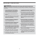
BEFORE YOU BEGIN Thank you for selecting the revolutionary NORDICTRACK® E 9.0 elliptical. The E 9.0 elliptical provides an impressive selection of features designed to make your workouts at home more effective and enjoyable. reading this manual, please see the front cover of this manual. To help us assist you, note the product model number and serial number before contacting us. The model number and the location of the serial number decal are shown on the front cover of this manual.
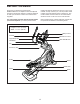
PART IDENTIFICATION CHART Use the drawings below to identify the small parts needed for assembly. The number in parentheses below each drawing is the key number of the part, from the PART LIST near the end of this manual. The number following the key number is the quantity needed for assembly. Note: If a part is not in the hardware kit, check to see if it has been preassembled. Extra parts may be included.
ASSEMBLY • Assembly requires two persons. • In addition to the included tool(s), assembly requires the following tools: • Place all parts in a cleared area and remove the packing materials. Do not dispose of the packing materials until you complete all assembly steps. one Phillips screwdriver one adjustable wrench • To identify small parts, see page 5. one rubber mallet • Assembly may be easier if you have your own set of wrenches. To avoid damaging parts, do not use power tools. 1.
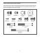
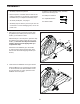
3. Remove the screws (not shown) and the shipping bracket (not shown) from the rear of the Frame (1). Discard the screws. 3 With the help of a second person, place the shipping bracket (not shown) under the rear of the Frame (1). Have the second person hold the Frame to prevent it from tipping while you complete this step. 5 Orient the Rear Stabilizer (5) so that the welded tubes are in the locations shown. 1 Attach the Rear Stabilizer (5) to the Frame (1) with two M10 x 75mm Screws (119).
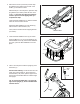
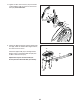
6. Tip: Avoid pinching the Main Wire (110). Set the Upright (4) on the Frame (1). 6 82 Attach the Upright (4) with four M8 x 19mm Screws (82) and four M8 Star Washers (122). 4 122 110 Avoid pinching the Main Wire (110) 7. Orient the Lower Upright Cover (56) as shown. 1 7 Press the Lower Upright Cover (56) into the Shield Cover (75).
8. Identify the Left and Right Inner Covers (55, 68), which are marked with “Left” and “Right” stickers, and orient them as shown. 8 55 Slide the Left Inner Cover (55) onto the left side of the Upright (4). Then, slide the Right Inner Cover (68) onto the right side of the Upright. 4 68 9. Using a small plastic bag to keep your fingers clean, apply some of the included grease to the Pivot Axle (35) and to two Wave Washers (95) (only one is shown).
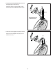
. Tighten an M8 x 16mm Screw (120) and an M8 x 25mm Washer (98) into each end of the Pivot Axle (35) at the same time. 10 120 98 35 98 120 11. Identify the Right Pedal (49) and the Right Pedal Arm (58), which are marked with “Right” stickers, and orient them as shown. 11 49 Attach the Right Pedal (49) to the Right Pedal Bracket (139) on the Right Pedal Arm (58) with six M6 x 10mm Screws (121). 58 139 Repeat this step for the Left Pedal (not shown) and the Left Pedal Arm (not shown).
12. Orient the Left Pedal Arm (44) as shown. 12 Apply grease to the axle on the Left Pedal Arm (44). 44 Attach the Left Pedal Arm (44) to the Left Roller Arm (12) with an M8 x 16mm Screw (120), a Roller Arm Cover (81), and an M8 x 25mm Washer (98). Grease 12 Repeat this step for the Right Pedal Arm (not shown). 120 98 13. Tip: Do not insert the Right Upper Body Arm (61) into the Right Upper Body Leg (36) until step 14. 81 13 Orient the Right Upper Body Leg (36) as shown.
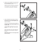
14. Insert the Right Upper Body Arm (61) into the Right Upper Body Leg (36). 14 Attach the Right Upper Body Arm (61) with two M8 x 35mm Bolts (96) and two M8 Locknuts (102). Make sure that the Locknuts are in the hexagonal holes. 96 Repeat this step on the other side of the elliptical. 36 See step 13. Tighten the M8 x 16mm Screws (120). 61 Hexagonal Holes 102 15. Attach the Right Inner Cover (68) to the Right Upper Body Arm (61) with a #8 x 3/4" Screw (123).
16. Untie and discard the wire tie on the Main Wire (110). 16 7 While a second person holds the Console (7) near the Upright (4), connect the wires on the Console to the Main Wire (110) and to the Right and Left Sensor Wires (63, 69). 63, 69 Insert the excess wire into the Upright (4) or into the Console (7). 110 4 17. Tip: Avoid pinching the wires. Attach the Console (7) to the Upright (4) with four #8 x 1/2" Screws (124). 17 7 Avoid pinching the wires 124 4 124 18.
19. Orient the Front Upright Cover (91) as shown. 19 123 Press the Front Upright Cover (91) into the Rear Upright Cover (80). 91 Attach the Front Upright Cover (91) to the Upright (4) with a #8 x 3/4" Screw (123). 4 80 20. Make sure that all parts are properly tightened before you use the elliptical. Note: After assembly is completed, some extra parts may be left over. Place a mat beneath the elliptical to protect the floor.
THE CHEST HEART RATE MONITOR HOW TO PUT ON THE HEART RATE MONITOR The heart rate monitor consists of a chest strap and a sensor. Insert the tab on one end of the chest strap into the hole in one end of the sensor as shown. Then, press the end of the sensor under the buckle on the chest strap. The tab should be flush with the front of the sensor.
HOW TO USE THE ELLIPTICAL HOW TO PLUG IN THE POWER CORD HOW TO MOVE THE ELLIPTICAL This product must be grounded. If it should malfunction or break down, grounding provides a path of least resistance for electric current to reduce the risk of electric shock. This product’s power cord has an equipment-grounding conductor and a grounding plug. Due to the size and weight of the elliptical, moving it requires two persons.
HOW TO ADJUST THE POSITIONS OF THE PEDALS HOW TO EXERCISE ON THE ELLIPTICAL To mount the elliptical, hold the upper body arms or the handlebars and step onto the pedal that is in the lower position. Then, step onto the other pedal. Push the pedals until they begin to move with a continuous motion. Note: The crank arms can turn in either direction. It is recommended that you turn the crank arms in the direction shown by the arrow; however, for variety, you can turn the crank arms in the opposite direction.
CONSOLE DIAGRAM FEATURES OF THE CONSOLE The advanced console offers an array of features designed to make your workouts more effective and enjoyable. When you use the manual mode of the console, you can change the resistance of the pedals and the incline of the ramp with the touch of a button. While you exercise, the console will display continuous exercise feedback. You can also measure your heart rate using the handgrip heart rate monitor or the included chest heart rate monitor.
HOW TO TURN ON THE POWER HOW TO USE THE MANUAL MODE IMPORTANT: If the elliptical has been exposed to cold temperatures, allow it to warm to room temperature before turning on the power. If you do not do this, you may damage the console displays or other electrical components. 1. Begin pedaling or press any button on the console to turn on the console. See HOW TO TURN ON THE POWER at the left. 2. Select the manual mode. Plug in the power cord (see HOW TO PLUG IN THE POWER CORD on page 16).
4. Follow your progress with the display. Stride—This display mode will show the total number of strides you have pedaled. The display can show the following workout information: Time—When the manual mode is selected, this display mode will show the elapsed time. When a workout is selected, this display mode will show the time remaining in the workout. The matrix offers several display tabs. Press the Display button until the desired tab is shown.
When a wireless iFit Live module is connected, the wireless symbol at the top of the display will show the strength of your wireless signal. Four arcs indicate full signal strength. When your pulse is detected, a heart symbol in will flash in the display each time your heart beats, one or two dashes will appear, and then your heart rate will be shown. For the most accurate heart rate reading, hold the contacts for at least 15 seconds.
HOW TO USE A TARGET TONING WORKOUT At the end of each segment of the workout, a series of tones will sound and the next segment of the profile will begin to flash. If a different resistance level, ramp incline level, and/or target rpm is programmed for the next segment, the resistance level, ramp incline level, and/or target rpm will appear in the display for a few seconds to alert you. The resistance of the pedals and the incline level of the ramp will then change. 1.
HOW TO USE AN IFIT LIVE WORKOUT 5. Select an iFit Live workout. You must have an iFit Live module to use an iFit Live workout. To select an iFit Live workout, press one of the iFit Live buttons. Note: Before some workouts will download, you must go to www.iFit.com and add them to your schedule. To purchase an iFit Live module at any time, go to www.iFit.com or call the telephone number on the front cover of this manual. Press the iFit Live button to download the next workout in your schedule.
HOW TO USE THE SOUND SYSTEM 7. Follow your progress with the display. To play music or audio books through the console sound system while you exercise, plug the included audio cable into the jack on the console and into a jack on your MP3 player or CD player; make sure that the audio cable is fully plugged in. See step 4 on page 20. The My Trail tab will show a map of the trail you are walking or running or it will show a track and the number of laps you complete.
HOW TO CHANGE CONSOLE SETTINGS 6. Select an audio setting for the voice of the personal trainer if desired. The console features a user mode that allows you to view usage information, select a unit of measurement, and adjust the contrast level of the display. Press the decrease button to view the audio setting for the voice of the personal trainer. The currently selected audio setting for the voice of the personal trainer will appear in the display.
FCC INFORMATION This equipment has been tested and found to comply with the limits for a Class B digital device, pursuant to part 15 of the FCC Rules. These limits are designed to provide reasonable protection against harmful interference in a residential installation. This equipment generates, uses, and can radiate radio frequency energy and, if not installed and used in accordance with the instructions, may cause harmful interference to radio communications.
MAINTENANCE AND TROUBLESHOOTING Inspect and tighten all parts of the elliptical regularly. Replace any worn parts immediately. HOW TO ADJUST THE DRIVE BELT If the pedals slip while you are pedaling, even while the resistance is adjusted to the highest level, the drive belt may need to be adjusted. To clean the elliptical, use a damp cloth and a small amount of mild soap. IMPORTANT: To avoid damage to the console, keep liquids away from the console and keep the console out of direct sunlight.
Loosen the M6 x 12mm Hex Screw (85) and the M10 x 58mm Hex Bolt (86). Then, remove the right Crank Arm (20). Gently move the right Crank Arm and the Right Roller Arm (45) out of the way. Do not misplace the Key (78) while removing the Crank Arm. HOW TO ADJUST THE REED SWITCH If the console does not display correct feedback, the reed switch should be adjusted. 86 78 85 To adjust the reed switch, first remove all the M4 x 16mm Screws (104) from the left Disc (71). Then, gently remove the left Disc.
EXERCISE GUIDELINES Burning Fat—To burn fat effectively, you must exercise at a low intensity level for a sustained period of time. During the first few minutes of exercise, your body uses carbohydrate calories for energy. Only after the first few minutes of exercise does your body begin to use stored fat calories for energy. If your goal is to burn fat, adjust the intensity of your exercise until your heart rate is near the lowest number in your training zone.
PART LIST Key No. Qty. 1 2 3 4 5 6 7 8 9 10 11 12 13 14 15 16 17 18 19 20 21 22 23 24 25 26 27 28 29 30 31 32 33 34 35 36 37 38 39 40 41 42 43 44 45 46 47 48 49 50 1 1 1 1 1 1 1 1 1 1 2 1 1 1 1 1 1 1 1 2 2 1 1 1 1 1 1 1 1 6 1 2 2 2 1 1 1 1 1 2 1 1 2 1 1 1 1 1 1 1 Model No. NTEL01011.1 R1011A Description Key No. Qty.
Key No. Qty. 101 102 103 104 105 106 107 108 109 110 111 112 113 114 115 116 117 118 119 120 121 122 123 124 125 126 127 128 129 130 1 10 1 46 4 2 4 2 1 1 2 1 1 1 4 2 30 1 2 18 12 4 11 6 2 2 14 2 2 1 Description Key No. Qty. Idler Screw M8 Locknut M3.
52 144 144 120 146 142 121 148 66 140 44 145 141 121 138 147 14 54 123 104 137 137 104 120 53 98 96 120 70 59 126 51 57 136 70 21 99 59 98 47 33 102 95 104 98 81 120 104 57 37 104 98 104 123 133 12 120 53 55 120 46 53 104 48 104 80 137 99 147 135 76 104 133 104 137 104 35 123 104 104 104 91 71 75 128 104 104 60 104 56 73 104 EXPLODED DRAWING A Model No. NTEL01011.
104 149 105 20 78 86 85 150 92 5 113 98 119 42 105 149 104 120 98 72 30 108 32 28 29 125 129 102 124 40 107 15 99 92 132 151 38 104 31 98 106 104 72 129 65 120 30 30 151 88 39 102 32 22 125 108 97 13 118 105 90 89 23 93 50 111 100 132 26 94 43 64 103 27 34 102 102 24 83 40 111 17 106 16 92 6 116 79 62 104 25 109 101 1 18 43 99 120 19 92 105 99 98 20 78 150 116 34 85 86 120 84 EXPLODED DRAWING B Model No.
127 104 104 126 127 127 34 120 21 33 104 77 104 104 74 51 81 104 104 128 127 98 57 60 104 127 57 143 104 104 144 145 45 52 137 137 147 104 104 71 135 144 140 142 141 139 53 146 121 120 133 98 104 99 133 123 120 87 58 68 49 137 104 96 95 70 41 104 137 99 147 120 61 104 104 98 53 70 36 59 59 102 120 53 136 120 98 123 67 EXPLODED DRAWING C Model No. NTEL01011.
115 93 117 3 79 35 127 79 134 115 11 127 115 117 127 117 93 10 117 9 79 127 115 117 117 79 7 117 2 117 117 124 117 124 117 30 8 4 117 110 123 104 69 112 123 82 104 63 130 114 122 30 131 EXPLODED DRAWING D Model No. NTEL01011.
ORDERING REPLACEMENT PARTS To order replacement parts, please see the front cover of this manual.