www.nordictrack.com Model No. NTEL07808.4 Serial No. Write the serial number in the space above for reference. Serial Number Decal (underside of frame) QUESTIONS? If you have questions, or if parts are damaged or missing, DO NOT CONTACT THE STORE; please contact Customer Care. IMPORTANT: Please register this product (see the limited warranty on the back cover of this manual) before contacting Customer Care. 1-800-TO-BE-FIT CALL TOLL-FREE: (1-800-862-3348) Mon.–Fri. 6 a.m.–6 p.m. MT Sat. 8 a.m.–4 p.
TABLE OF CONTENTS WARNING DECAL PLACEMENT . . . . . . . . . . . . . . . . . . . . . . . . . . . . . . . . . . . . . . . . . . . . . . . . . . . . . . . . . . . . . .2 IMPORTANT PRECAUTIONS . . . . . . . . . . . . . . . . . . . . . . . . . . . . . . . . . . . . . . . . . . . . . . . . . . . . . . . . . . . . . . . .3 BEFORE YOU BEGIN . . . . . . . . . . . . . . . . . . . . . . . . . . . . . . . . . . . . . . . . . . . . . . . . . . . . . . . . . . . . . . . . . . . . . .4 ASSEMBLY . . . . . . . . . . . . .
IMPORTANT PRECAUTIONS WARNING: To reduce the risk of serious injury, read all important precautions and instructions in this manual and all warnings on your elliptical before using your elliptical. ICON assumes no responsibility for personal injury or property damage sustained by or through the use of this product. 1. Before beginning any exercise program, consult your physician. This is especially important for persons over age 35 or persons with pre-existing health problems. 9.
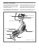
BEFORE YOU BEGIN reading this manual, please see the front cover of this manual. To help us assist you, note the product model number and serial number before contacting us. The model number and the location of the serial number decal are shown on the front cover of this manual. Thank you for selecting the revolutionary NordicTrack® E7 SV FRONT DRIVE elliptical.
ASSEMBLY Assembly requires two persons. Place all parts of the elliptical in a cleared area and remove the packing materials. Do not dispose of the packing materials until assembly is completed. In addition to the included tool(s), assembly requires a Phillips screwdriver wrenches , and a rubber mallet . , two adjustable See the drawings below to identify the small parts needed for assembly.
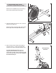
1. 1 To make assembly easier, read the information on page 5 before you begin. Attach the Front Stabilizer (6) to the Frame (1) with two M8 x 80mm Patch Screws (84). 6 84 1 2. Orient the Ramp (3) as shown. Then, insert the Ramp into the Frame (1). 2 Attach the Ramp (3) with five M8 x 19mm Patch Screws (82) and five M8 Split Washers (83). 82 83 1 3 83 3. While a second person holds the Upright (4) near the Frame (1), connect the Upper Wire Harness (110) to the Lower Wire Harness (111).
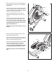
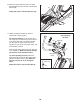
4. Apply a small amount of the included grease to the right Crank Arm (20) and to a 19mm Wave Washer (66). 4 Orient a Crank Arm Spacer (55) so that the flat end is facing away from the elliptical. Slide the Crank Arm Spacer and the 19mm Wave Washer (66) onto the right Crank Arm (20). 20 Flat End Identify the Right Roller Arm (59), which is marked with a “Right” sticker, and orient it as shown. Slide the Right Roller Arm (59) onto the right Crank Arm (20).
6. Identify the Right Handlebar (61) and the Right Handlebar Leg (60), which are marked with “Right” stickers, and orient them as shown. Make sure that the hexagonal holes are in the indicated location. 6 61 Slide the Right Handlebar (61) onto the Right Handlebar Leg (60). 102 Attach the Right Handlebar (61) with two M8 x 38mm Bolts (96) and two M8 Locknuts (102). Make sure that the Locknuts are in the hexagonal holes.
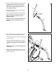
8. Attach an Outer Handlebar Cover (67) and the Inner Handlebar Cover (68) around the Right Handlebar Leg (60) with two M4 x 16mm Screws (104). 8 Repeat this step for the other side of the elliptical. 104 104 68 9. Apply a small amount of grease to the axle on the Right Handlebar Leg (60) and to a 19mm Wave Washer (66). 60 67 9 Identify the Right Pedal Arm (58), which is marked with a “Right” sticker, and orient it as shown.
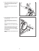
. Attach the Right Pedal Arm (58) to the Right Pedal Bracket (64) with two M10 x 45mm Patch Screws (99). 10 44 Repeat this step for the Left Pedal Arm (44). 64 58 99 11. Identify the Right Pulse Bar (9), which is marked with a “Right” sticker. See the inset drawing. Locate the wire tie in the Upright (4). Tie the lower end of the wire tie to the Pulse Wire (63) in the Right Pulse Bar (9). Next, pull the upper end of the wire tie upward out of the top of the Upright.
12. Attach the Water Bottle Holder (37) to the Upright (4) with two M4 x 16mm Screws (104). 12 4 104 104 37 13. While a second person holds the Console (7) near the Upright (4), connect the console wire to the Upper Wire Harness (110). Then, connect the console pulse wires to the Pulse Wires (63). 13 7 Avoid pinching the wires Console Wire Insert the excess wire downward into the Upright (4). Tip: Avoid pinching the wires. Attach the Console (7) to the Upright (4) with four M4 x 16mm Screws (104).
14. Plug the Power Adapter (112) into the receptacle in the Console (7). To plug the Power Adapter (112) into an outlet, see HOW TO PLUG IN THE POWER ADAPTER on page 13. 14 7 112 Note: The console can also be operated with four 1.5V D batteries (not included); alkaline batteries are recommended. Locate the battery cover on the back of the Console. Remove the battery cover, and insert the batteries into the battery compartment.
HOW TO USE THE ELLIPTICAL HOW TO PLUG IN THE POWER ADAPTER HOW TO MOVE THE ELLIPTICAL IMPORTANT: If the elliptical has been exposed to cold temperatures, allow it to warm to room temperature before plugging in the power adapter. If you do not do this, you may damage the console displays or other electronic components. Due to the size and weight of the elliptical exerciser, moving it requires two persons.
HOW TO EXERCISE ON THE ELLIPTICAL HOW TO CHANGE THE INCLINE OF THE RAMP To mount the elliptical, hold the handlebars and step onto the pedal that is in the lower position. Then, step onto the other pedal. Push the pedals until they begin to move with a continuous motion. Note: The crank arms can turn in either direction. It is recommended that you turn the crank arms in the direction shown by the arrow; however, for variety, you can turn the crank arms in the opposite direction.
CONSOLE DIAGRAM FEATURES OF THE CONSOLE out. iFit workouts control the resistance of the pedals while the voice of a personal trainer coaches you through your workouts. iFit cards are available separately. To purchase iFit cards, go to www.iFit.com or see the front cover of this manual. iFit cards are also available at select stores. The revolutionary console offers an array of features designed to make your workouts more effective and enjoyable.
The lower right display—The lower right display can show the your pedaling speed (in miles or kilometers per hour) and the approximate number of calories that you have burned. The display also shows your heart rate when you use the handgrip pulse sensor (see step 5 on page 17). HOW TO USE THE MANUAL MODE 1. Begin pedaling or press any button on the console to turn on the console. A moment after you begin pedaling or press a button, a tone will sound, and the display will light. 2.
5. Measure your heart rate if desired. HOW TO USE A TRAINER WORKOUT If there are sheets of plastic on the Contacts metal contacts on the handgrip pulse sensor, remove the plastic. To measure your heart rate, hold the handgrip pulse sensor with your palms resting against the metal contacts. Avoid moving your hands or gripping the contacts tightly. 1. Begin pedaling or press any button on the console to turn on the console.
HOW TO USE A WEIGHT LOSS WORKOUT If the resistance level for the current segment is too high or too low, you can manually override the setting by pressing the Silent Magnetic Resistance buttons. IMPORTANT: When the current segment of the workout ends, the pedals will automatically adjust to the resistance level programmed for the next segment. 1. Begin pedaling or press any button on the console to turn on the console.
HOW TO USE AN IFIT WORKOUT If the resistance level for the current segment is too high or too low, you can manually override the setting by pressing the Silent Magnetic Resistance buttons. IMPORTANT: When the current segment of the workout ends, the pedals will automatically adjust to the resistance level programmed for the next segment. iFit cards are available separately. To purchase iFit cards, go to www.iFit.com or see the front cover of this manual. iFit cards are also available at select stores 1.
HOW TO USE THE SOUND SYSTEM The upper display will show the currently selected backlight option. Press the Silent Magnetic Resistance increase button repeatedly to select the desired backlight option. To play music or audio books through the console sound system while you exercise, plug an audio cable (not included) into the jack on the console and into a jack on your MP3 player or CD player; make sure that the audio cable is fully plugged in. 3. Select a unit of measurement if desired.
MAINTENANCE AND TROUBLESHOOTING HOW TO ADJUST THE REED SWITCH Inspect and tighten all parts of the elliptical regularly. Replace any worn parts immediately. If the console does not display correct feedback, the reed switch should be adjusted. To adjust the reed switch, first use a flat screwdriver to pry the left disc carefully away from the left disc mount. Then, remove the left disc. To clean the elliptical, use a damp cloth and a small amount of mild soap.
EXERCISE GUIDELINES WARNING: Before beginning this Burning Fat—To burn fat effectively, you must exercise at a low intensity level for a sustained period of time. During the first few minutes of exercise, your body uses carbohydrate calories for energy. Only after the first few minutes of exercise does your body begin to use stored fat calories for energy. If your goal is to burn fat, adjust the intensity of your exercise until your heart rate is near the lowest number in your training zone.
PART LIST Key No. Qty. 1 2 3 4 5 6 7 8 9 10 11 12 13 14 15 16 17 18 19 20 21 22 23 24 25 26 27 28 29 30 31 32 33 34 35 36 37 38 39 40 41 42 43 44 45 46 47 48 49 50 1 1 1 1 3 1 1 1 1 1 1 1 1 1 4 1 1 1 1 2 13 1 1 1 1 1 1 1 1 4 1 2 1 2 1 4 1 1 2 6 2 4 2 1 1 1 1 1 2 2 Description Key No. Qty.
Key No. Qty. 101 102 103 104 105 106 107 108 109 110 2 12 1 16 10 1 4 12 2 1 Description Key No. Qty. M8 x 20mm Washer M8 Locknut M3.
EXPLODED DRAWING A 108 78 102 109 86 81 85 42 20 40 1 82 83 83 83 82 83 102 91 82 88 102 41 32 97 98 30 79 41 94 7 102 84 19 34 18 23 103 90 21 26 27 24 21 25 93 37 85 86 93 5 78 15 111 109 108 11 82 15 112 12 14 16 21 32 97 25 21 82 13 3 98 83 10 33 31 36 83 102 9 96 104 82 81 20 102 4 36 104 35 63 104 102 96 29 2 30 8 6 43 89 92 28 113 34 39 87 43 69 106 22 91 115 110 39 42 80 63 69 38 40 Model No.
EXPLODED DRAWING B Model No. NTEL07808.
EXPLODED DRAWING C Model No. NTEL07808.
ORDERING REPLACEMENT PARTS To order replacement parts, please see the front cover of this manual.