www.nordictrack.com Model No. NTEL09109.6 Serial No. Write the serial number in the space above for reference. Serial Number Decal QUESTIONS? If you have questions, or if parts are damaged or missing, DO NOT CONTACT THE STORE; please contact Customer Care. IMPORTANT: Please register this product (see the limited warranty on the back cover of this manual) before contacting Customer Care. 1-800-TO-BE-FIT CALL TOLL-FREE: (1-800-862-3348) Mon.–Fri., 6 a.m.–6 p.m. MT Sat. 8 a.m.–4 p.m.
TABLE OF CONTENTS WARNING DECAL PLACEMENT . . . . . . . . . . . . . . . . . . . . . . . . . . . . . . . . . . . . . . . . . . . . . . . . . . . . . . . . . . . . . .2 IMPORTANT PRECAUTIONS . . . . . . . . . . . . . . . . . . . . . . . . . . . . . . . . . . . . . . . . . . . . . . . . . . . . . . . . . . . . . . . .3 BEFORE YOU BEGIN . . . . . . . . . . . . . . . . . . . . . . . . . . . . . . . . . . . . . . . . . . . . . . . . . . . . . . . . . . . . . . . . . . . . . .4 ASSEMBLY . . . . . . . . . . . . .
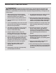
IMPORTANT PRECAUTIONS WARNING: To reduce the risk of serious injury, read all important precautions and instructions in this manual and all warnings on your elliptical before using your elliptical. ICON assumes no responsibility for personal injury or property damage sustained by or through the use of this product. 1. Before beginning any exercise program, consult your physician. This is especially important for persons over age 35 or persons with pre-existing health problems. 9.
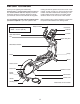
BEFORE YOU BEGIN reading this manual, please see the front cover of this manual. To help us assist you, note the product model number and serial number before contacting us. The model number and the location of the serial number decal are shown on the front cover of this manual. Thank you for selecting the revolutionary NORDICTRACK® AUDIOSTRIDER 990 PRO elliptical.
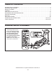
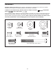
ASSEMBLY Assembly requires two persons. Place all parts of the elliptical in a cleared area and remove the packing materials. Do not dispose of the packing materials until assembly is completed. In addition to the included tool(s), assembly requires a Phillips screwdriver wrench , and a rubber mallet . , an adjustable Use the drawings below to identify the small parts needed for assembly.
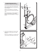
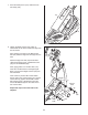
1. 1 To make assembly easier, read the information on page 5 before you begin. 100 Have a second person hold the Folding Frame (2) to prevent the elliptical from tipping until this step is completed. Handle 4 Attach the Rear Stabilizer (4) to the Folding Frame (2) with two M10 x 95mm Patch Screws (100). Next, hold the handle on the Rear Stabilizer (4), press the Latch Button (67), and unfold the elliptical so that the Rear Stabilizer is resting on the floor. 2 67 2.
3. Orient the Upright (5) and the Top Cover (27) as shown, and slide the Top Cover upward onto the Upright. 3 Wire Tie Have a second person hold the Upright (5) and the Top Cover (27) near the Main Frame (1). Avoid pinching the Wire Harness (60) Locate the wire tie in the Upright (5). Tie the lower end of the wire tie to the Wire Harness (60). Next, pull the upper end of the wire tie until the Wire Harness is routed through the Upright.
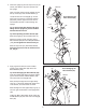
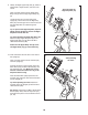
5. Identify the Right Pedal (14), the Right Gel Pad (55), and the Right Pedal Arm (12), which are marked with “Right” stickers, and orient them as shown. 5 14 Set the Right Gel Pad (55) on the Right Pedal Arm (12). Then, set the Right Pedal (14) on the Right Gel Pad. 55 Attach the Right Pedal (14) to the Right Pedal Arm (12) with two M6 x 50mm Patch Screws (62), two M6 x 12mm Patch Screws (111), and four M6 Washers (112).
7. Press the Ramp Cover (131) downward onto the Ramp (130). 7 131 130 8. Identify the Right Link Arm (43), which is marked with an “R” sticker. Orient the Right Link Arm as shown. 8 Apply grease to the axle on the Right Pedal Arm (12). Slide the Right Link Arm (43) onto the axle. Attach the Right Link Arm (43) with an M8 x 16mm Patch Screw (102), a Small Axle Cover (56), and an M8 Washer (95). Next, apply grease to a Link Arm Axle (114).
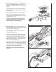
9. Identify the Right Upper Body Arm (8), which is marked with a “Right” sticker, and orient it as shown. 9 Avoid pinching the Right Grip Wire (45) 9 Have a second person hold the Right Upper Body Arm (8) near the Right Upper Body Leg (6). Locate the wire tie in the right side of the Upright (5). Tie the wire tie to the Right Grip Wire (45). Pull the upper end of the wire tie until the Right Grip Wire is routed through the Upright.
. Attach the Front Upright Cover (24) to the Upright (5) with four M4 x 16mm Screws (106). 11 24 106 12. Attach the Rear Upright Cover (25) around the Upright (5) by pressing the tabs on the Rear Upright Cover into the Front Upright Cover (24). 5 12 24 5 25 13. Make sure that all parts of the elliptical are properly tightened. Note: Some hardware may be left over after assembly is completed. To protect the floor or carpet from damage, place a mat under the elliptical.
HOW TO USE THE ELLIPTICAL HOW TO PLUG IN THE POWER CORD HOW TO FOLD AND UNFOLD THE ELLIPTICAL This product must be grounded. If it should malfunction or break down, grounding provides a path of least resistance for electric current to reduce the risk of electric shock. This product is equipped with a cord having an equipment-grounding conductor and a grounding plug. Plug the power cord into an appropriate outlet that is properly installed and grounded in accordance with all local codes and ordinances.
HOW TO MOVE THE ELLIPTICAL HOW TO EXERCISE ON THE ELLIPTICAL To move the elliptical, first fold it as described on page 12. Next, stand in front of the elliptical, hold the upright, and place one foot against one of the wheels. Pull the upright until the elliptical rolls on the wheels. Carefully move the elliptical to the desired position, and then lower it to the floor. To mount the elliptical, hold the upper body arms and step onto the pedal that is in the lowest position.
CONSOLE DIAGRAM FEATURES OF THE CONSOLE With the iFit Live mode, you can download personalized workouts, create your own workouts, track your workout results, and access many other features. See www.iFit.com for complete information. The advanced console offers an array of features designed to make your workouts more effective and enjoyable. To purchase an iFit Live module at any time, go to www.iFit.com or call the telephone number on the front cover of this manual.
HOW TO TURN ON THE POWER 3. Change the resistance of the pedals and the incline of the ramp as desired. IMPORTANT: If the elliptical has been exposed to cold temperatures, allow it to warm to room temperature before turning on the power. If you do not do this, you may damage the console displays or other electrical components. Plug in the power cord (see HOW TO PLUG IN THE POWER CORD on page 12). Next, locate the power switch on the frame near the power cord.
Resistance—This display mode will show the resistance level of the pedals for a few seconds each time the resistance level changes. If the display does not show your heart rate, make sure that your hands are positioned as described. Be careful not to move your hands excessively or squeeze the contacts tightly. For optimal performance, clean the contacts using a soft cloth; never use alcohol, abrasives, or chemicals to clean the contacts.
HOW TO USE A PRESET WORKOUT When the first segment of the workout ends, the resistance level, ramp incline, and the target rpm for the second segment will appear in the display for a few seconds to alert you. The next segment of the profile will begin to flash, and the pedals will automatically adjust to the resistance level and the ramp incline for the next segment. 1. Begin pedaling or press any button on the console to turn on the console. See HOW TO TURN ON THE POWER on page 15. 2.
HOW TO USE THE IFIT TRAINING MODE HOW TO USE THE INFORMATION MODE The optional iFit Live module allows your console to communicate with your wireless network and unlocks exciting new features. For example, you can download personalized workouts, create your own workouts, track your workout results, and access many other features on the iFit Live website. To purchase an iFit Live module at any time, go to www.iFit.com or call the telephone number on the front cover of this manual.
MAINTENANCE AND TROUBLESHOOTING HOW TO ADJUST THE REED SWITCH Inspect and tighten all parts of the elliptical regularly. Replace any worn parts immediately. If the console does not display correct feedback, the reed switch should be adjusted. To clean the elliptical, use a damp cloth and a small amount of mild soap. IMPORTANT: To avoid damaging the console, keep liquids away from the console and keep the console out of direct sunlight. To adjust the reed switch, first unplug the power cord.
HOW TO ADJUST THE DRIVE BELT Next, remove the indicated M8 x 25mm Patch Screw (121), Large Axle Cover (113), M8 Washer (95), and Pedal Arm Sleeve (46). Using a flat screwdriver, carefully pry the left Disc (17) off the elliptical. If you can feel the pedals slip while you are pedaling, even when the resistance is adjusted to the highest level, the drive belt may need to be adjusted. To adjust the drive belt, first unplug the power cord.
EXERCISE GUIDELINES WARNING: Before beginning this Burning Fat—To burn fat effectively, you must exercise at a low intensity level for a sustained period of time. During the first few minutes of exercise, your body uses carbohydrate calories for energy. Only after the first few minutes of exercise does your body begin to use stored fat calories for energy. If your goal is to burn fat, adjust the intensity of your exercise until your heart rate is near the lowest number in your training zone.
SUGGESTED STRETCHES The correct form for several basic stretches is shown at the right. Move slowly as you stretch—never bounce. 1. Toe Touch Stretch 1 Stand with your knees bent slightly and slowly bend forward from your hips. Allow your back and shoulders to relax as you reach down toward your toes as far as possible. Hold for 15 counts, then relax. Repeat 3 times. Stretches: Hamstrings, back of knees and back. 2. Hamstring Stretch 2 Sit with one leg extended.
PART LIST Key No. Qty. 1 2 3 4 5 6 7 8 9 10 11 12 13 14 15 16 17 18 19 20 21 22 23 24 25 26 27 28 29 30 31 32 33 34 35 36 37 38 39 40 41 42 43 44 45 46 47 48 49 50 1 1 1 1 1 1 1 1 1 2 1 1 1 1 1 2 2 1 1 1 1 1 1 1 1 1 1 1 18 2 4 2 1 2 1 2 2 1 2 1 3 1 1 1 1 2 4 1 2 2 Description Key No. Qty.
Key No. Qty. 101 102 103 104 105 106 107 108 109 110 111 112 113 114 115 116 117 118 119 120 121 122 123 124 125 126 127 128 2 18 4 1 1 48 2 2 4 2 4 8 2 2 1 1 2 2 1 1 2 1 1 1 1 2 2 2 Description Key No. Qty. Small Snap Ring M8 x 16mm Patch Screw M8 Split Washer Left Grip Wire Pulse Wire M4 x 16mm Screw M10 x 25mm Button Screw M10 x 32mm Washer M8 x 16mm Button Screw M8 x 23.
102 25 49 51 31 30 50 9 127 13 113 58 144 128 52 53 95 106 31 58 56 102 102 62 95 15 44 95 47 112 10 58 121 104 102 46 58 54 112 26 30 114 47 111 31 62 112 58 11 7 54 33 27 95 12 111 102 32 101 31 40 56 25 55 10 48 34 112 102 103 106 62 111 112 14 101 32 102 106 57 118 5 103 47 102 105 58 47 58 114 106 43 56 121 52 106 51 50 56 127 128 53 102 102 45 35 58 95 8 49 58 102 102 95 54 59 95 113 95 58 6
41 26 37 100 115 116 4 129 75 73 86 125 39 99 76 86 75 98 41 2 96 97 94 86 87 74 72 70 85 69 106 82 90 91 61 68 106 37 119 71 88 84 109 78 87 81 76 77 92 79 80 38 89 122 94 60 83 133 64 29 67 86 39 147 132 131 108 86 42 65 124 41 148 145 136 109 117 66 109 110 107 132 130 29 141 141 120 106 117 140 138 93 139 126 110 109 36 16 64 145 137 140 23 106 93 146 36 63 64 142 142 135 3 134 143 100 143 142 123
17 27 106 106 29 29 106 20 106 106 19 106 106 106 106 106 106 106 106 29 29 18 106 29 22 106 21 17 106 106 EXPLODED DRAWING C Model No. NTEL09109.
ORDERING REPLACEMENT PARTS To order replacement parts, see the front cover of this manual.